Image sending/receiving device

a technology of image data and receiver, which is applied in the direction of digital output to print units, instruments, television systems, etc., can solve the problems of inability to select e or f as the resolution, and inability to output image data in the resolution e and

Inactive Publication Date: 2007-03-29
ONKYO KK
View PDF5 Cites 36 Cited by
  • Summary
  • Abstract
  • Description
  • Claims
  • Application Information

AI Technical Summary

Benefits of technology

[0028] If the connected image display device is in conformity with the first standard, it is determined that a set of compatible resolutions are not accurately stored in the image display device. Therefore, the image sending / receiving device registers, in the first storage section, all of the resolutions pre-stored in the second storage section, irrespective of the resolutions read out from the image display device. The image reproducing device reads out the set of resolutions from the first storage section, and displays the resolution setting screen based on the set of resolutions. Therefore, even if a set of resolutions are not accurately stored in the image display device, it is possible to display, on the resolution setting screen of the image reproducing device, all of the resolutions stored in the image sending / receiving device and to have the user select a resolution from among all the resolutions. Thus, it is possible to prevent a problem where image data cannot be sent from the image reproducing device.

Problems solved by technology

Therefore, a resolution that is compatible with the display device but is not stored in the ROM of the AV amplifier is not displayed on the resolution setting screen of the DVD player, and the DVD player cannot output image data in that resolution.
This problem is common in cases where a display device of the DVI standard is connected to an AV amplifier of the HDMI standard.
Therefore, it is not possible to select e or f as the resolution in which the DVD player outputs image data.
Thus, even though the display device is capable of displaying images in the resolutions e and f, the DVD player cannot output image data in the resolutions e and f.
Therefore, a display device conforming to the DVI standard may have only some or none of the available resolutions stored in the PROM, due to PROM capacity limitations.
Then, the resolutions compatible with the display device will not accurately be displayed on the resolution setting screen.
As a result, there will be some resolutions that are compatible with the display device but cannot be selected as resolutions in which the DVD player outputs image data, whereby the DVD player cannot output image data in such resolutions.

Method used


Image

  • Image sending/receiving device
  • Image sending/receiving device
  • Image sending/receiving device

Examples


first embodiment

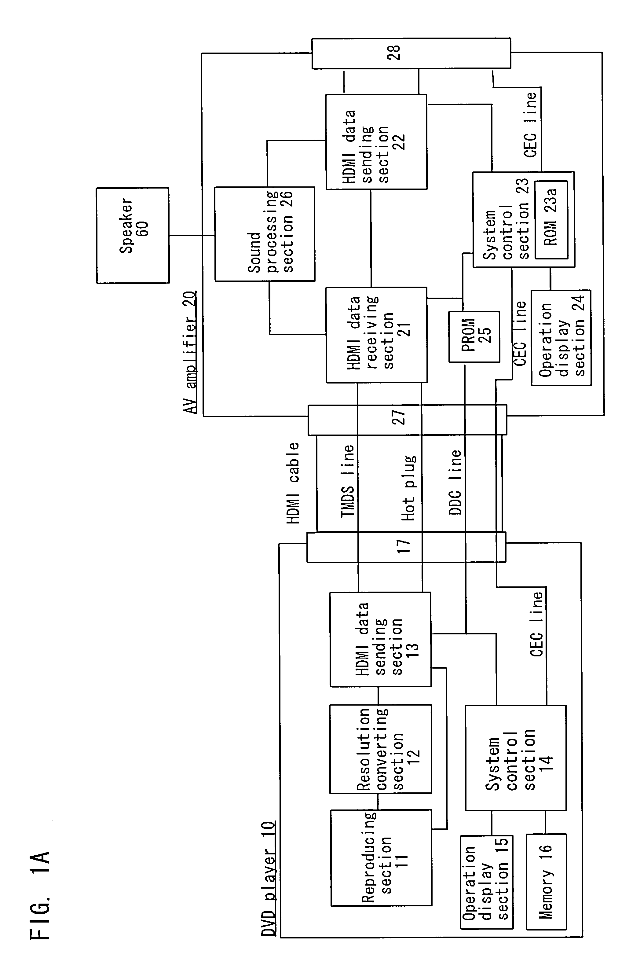
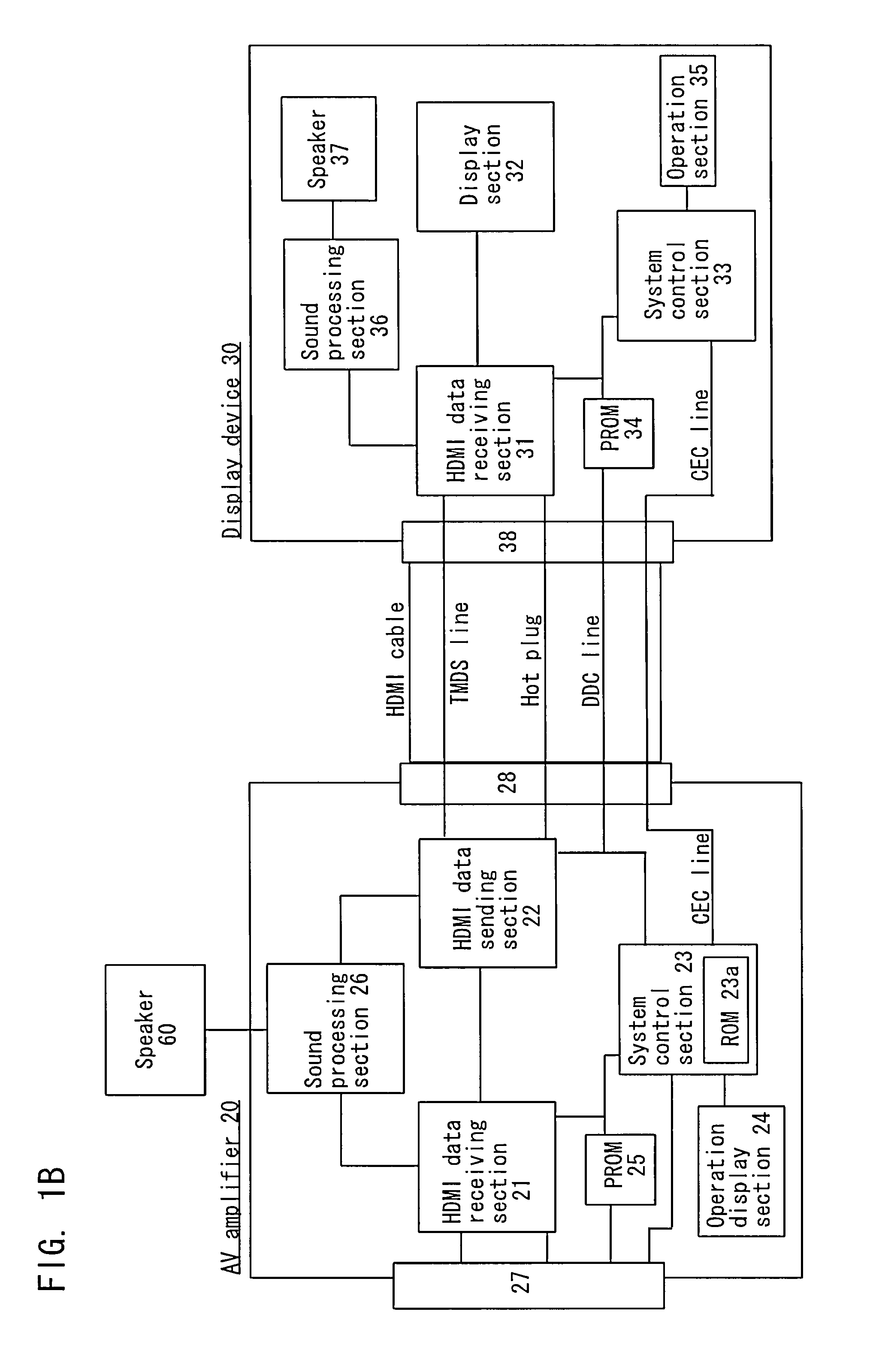
[0037]FIG. 1A is a schematic block diagram showing a DVD player 10 and an AV amplifier 20, and FIG. 1B is a schematic block diagram showing the AV amplifier 20 (the same AV amplifier as that shown in FIG. 1A) and a display device 30. The DVD player 10 and the AV amplifier 20 are in conformity with the HDMI standard, and are connected to each other via an HDMI cable. The display device 30 is in conformity with the HDMI standard or the DVI standard, and is connected to the AV amplifier 20 via an HDMI cable when it is of the HDMI standard or a DVI cable when it is of the DVI standard.

[0038] First, a configuration of the DVD player 10 will be described. The DVD player 10 includes a reproducing section 11, a resolution converting section 12, an HDMI data sending section 13, a system control section 14, an operation display section 15, a memory 16, and a connector section 17.

[0039] The reproducing section 11 reads out and decodes image data from a DVD disc (hereinafter referred to simpl...

second embodiment

[0098] A second embodiment of the present invention will now be described below. The basic configuration is the same as that of the first embodiment shown in FIGS. 1A and 1B, and will not be further described below. Only what is different from the first embodiment will be described below.

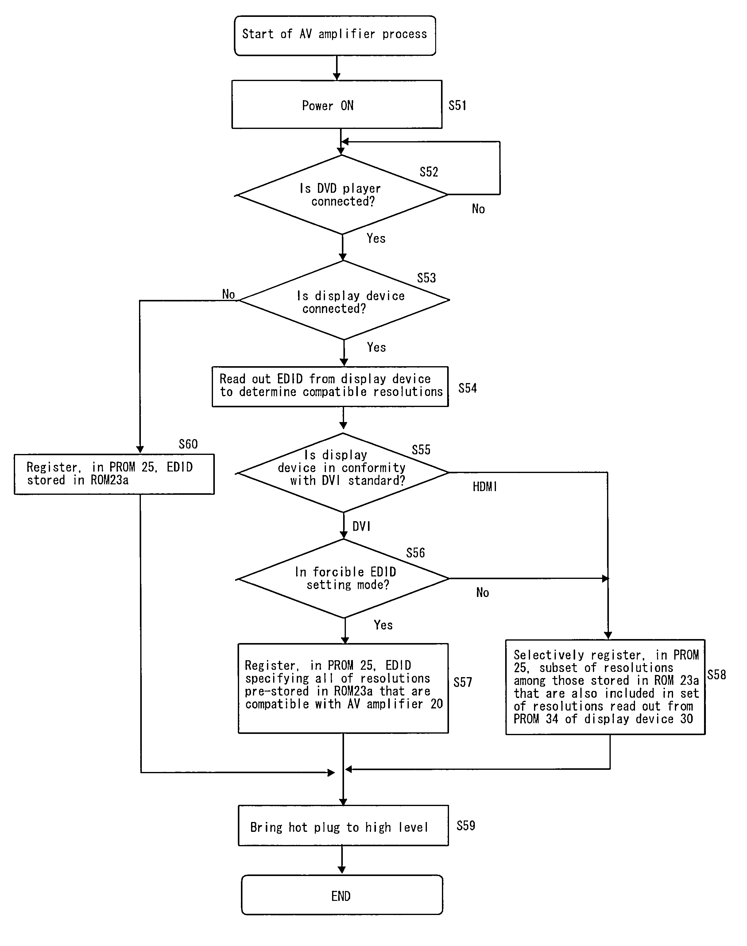
[0099] The system control section 23 has two modes of operation, i.e., a normal mode and a forcible EDID setting mode, for registering the EDID read out by the DVD player 10 in the PROM 25.

[0100] In the normal mode, a subset of resolutions among those pre-stored in the ROM 23a that are also included in the set of resolutions specified by the EDID read out from the PROM 34 of the display device 30 are registered in the PROM 25. Thus, a set of resolutions that are stored both in the AV amplifier 20 and in the display device 30 are registered in the PROM 25.

[0101] Specifically, where the resolutions pre-stored in the ROM 23a of the AV amplifier 20 are a, b, c and d and the resolutions stored in the ...


PUM


Abstract

An image sending/receiving device of the present invention includes: an image receiving section for receiving image data from an external image reproducing device connected to the image sending/receiving device; an image sending section for sending the image data to an external image display device connected to the image sending/receiving device; a first storage section for storing a set of resolutions to be read out by the image reproducing device; a second storage section in which a set of resolutions are pre-stored; a read-out section for reading out a set of resolutions pre-stored in the image display device from the image display device; and a resolution registration section for registering, in the first storage section, all of the resolutions read out by the read-out section or a subset of resolutions among those read out by the read-out section with which the image sending section is able to send data to the image display device.

Description

BACKGROUND OF THE INVENTION [0001] 1. Field of the Invention [0002] The present invention relates to an image sending / receiving device for registering a set of resolutions with which an image reproducing device can output reproduced image, based on a set of resolutions read out from an image display device and another set of resolutions pre-stored in the image sending / receiving device. [0003] 2. Description of the Related Art [0004]FIG. 6A shows a conventional system in which a DVD player, an AV amplifier and a display device, all conforming to the HDMI (High Definition Multimedia Interface) standard, are connected together via HDMI cables. The image data reproduced by the DVD player is output to the display device via the AV amplifier. [0005] The display device can use different display resolutions, and EDID (Extended Display Identification Data) specifying a set of resolutions (e.g., “XGA”, etc.) compatible with the display device is stored in a PROM (not shown) provided in the di...

Claims


Application Information

Patent Timeline
Patent Type & Authority Applications(United States)
IPC IPC(8): G06F3/12
CPCG09G5/006G09G2330/026G09G2370/047H04N5/46H04N5/775H04N5/85H04N21/4621H04N9/8063H04N21/42646H04N21/43632H04N21/43635H04N21/4402H04N9/8042
Inventor KITAYAMA, KOJIFUKUMA, HIROYUKI
Owner ONKYO KK
Why Eureka
Try Eureka