
Rapid part fabrication employing integrated components

a technology of integrated components and parts, applied in additive manufacturing processes, manufacturing tools, coatings, etc., can solve the problems of reducing the construction of complex objects to manageable, free-form fabrication reduces the construction of complex objects to high geometric complexity or intricacy, and the application of free-form fabrication technologies of the type described above is normally limited

Inactive Publication Date: 2007-03-29
THE BOEING CO
View PDF5 Cites 59 Cited by
  • Summary
  • Abstract
  • Description
  • Claims
  • Application Information

AI Technical Summary

Benefits of technology

The invention provides a method for manufacturing a part with an integrated component using computer automated, solid free-form fabrication. The process involves combining layers of material to form solid features of the part and interposing the component between the layers to integrate it into the finished part. The method can be carried out in three steps and uses fused deposition modeling or stereolithography for the fabrication process. The invention also includes a process for producing a part with a body and a component integrated into it by flowing heated thermoplastic material on top of each other and interposing the component between certain layers to fix it within the body. The CAD drawing file is used to generate a set of programmed instructions for the fabrication process. The technical effects of the invention include improved efficiency in manufacturing complex parts with integrated components.

Problems solved by technology

For example, objects can be formed with high geometric complexity or intricacy without the need for elaborate machine setup or final assembly.
Further, free-form fabrication reduces the construction of complex objects to manageable, straight forward and relatively fast processing.
Free-form fabrication technologies of the type described above are normally limited in their application to short production runs and monolithic parts.

Method used


Image

  • Rapid part fabrication employing integrated components
  • Rapid part fabrication employing integrated components
  • Rapid part fabrication employing integrated components

Examples


Embodiment Construction

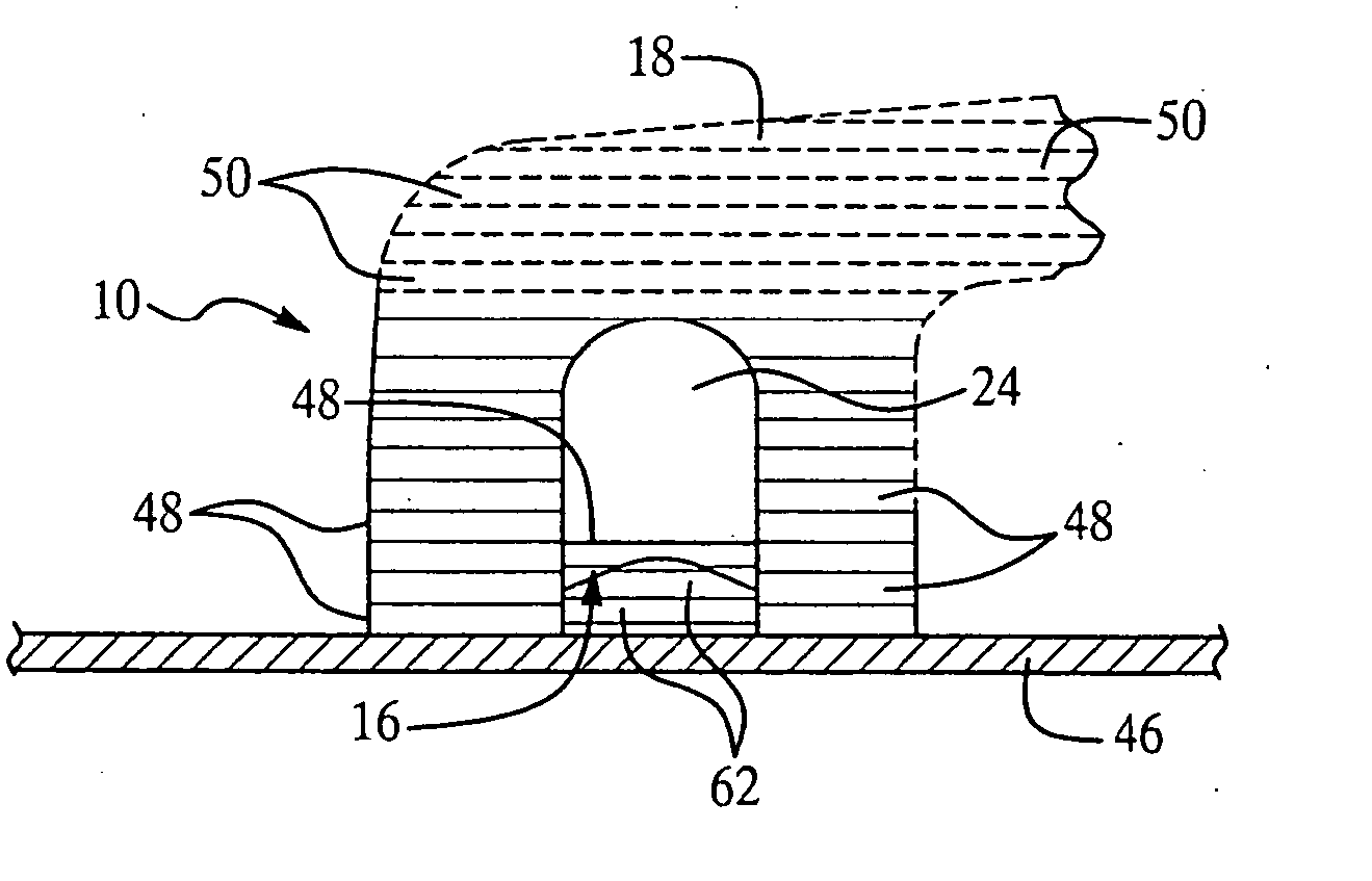
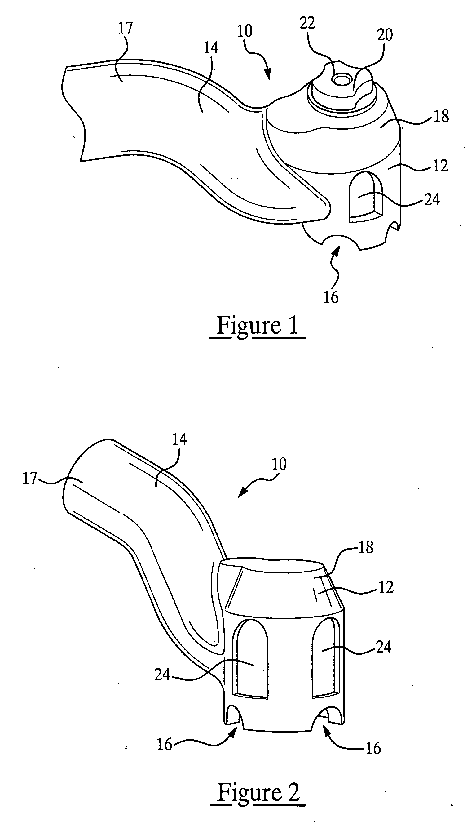
[0016] The present invention involves a method and process for manufacturing a part having an integrated or encapsulated component. An exemplary part that may be manufactured using the process of the present invention is shown in FIG. 1. A drill-guide tool, generally indicated by the numeral 10, is used guide a drill bit (not shown) and evacuate or remove chips that are produced when a hole is drilled in an object. The tool 10 includes a generally cylindrical, hollow head 12 and an open bottom intended to engage and cover an area of the object to be drilled, where the drill bit is intended to penetrate the object. A series of circumferentially spaced openings 16 are provided along the bottom of the head 12 which function to allow air to enter the head 12. The head 12 includes a domed top 18 provided with a central opening which receives a bushing 20 having a central through-hole 22 communicating with the open interior of head 12. The diameter of the through-hole 22 is essentially eq...


PUM

PropertyMeasurementUnit
plastic thermosettingaaaaaaaaaa
fused deposition modelingaaaaaaaaaa
moldingaaaaaaaaaa

Abstract

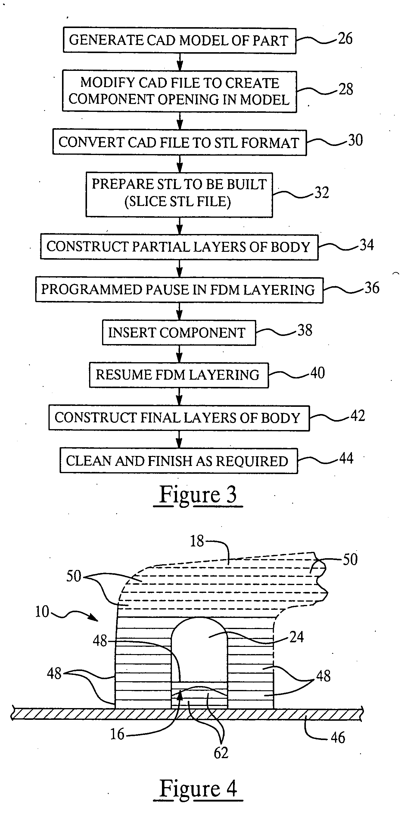
A part having an integrated, discrete component is produced by direct digital manufacturing and rapid, solid free-form fabrication techniques. A CAD file representing the part is modified to include an opening in the body of the part in which the component is to be inserted. The fabrication is performed by additive layering of a thermoplastic material, preferably using fused deposition modeling or stereolithography. The layering process is interrupted to allow the component to be inserted in the partially formed part, following which additional layers are added which secure the component in the part in place and complete the physical structure of the part.

Description

FIELD OF THE INVENTION [0001] This invention generally relates to manufacturing processes, and deals more particularly with a method for manufacturing a part having an integrated component. BACKGROUND OF THE INVENTION [0002] A wide array of manufactured parts incorporate individual components that are integrated or encapsulated into the body of the part during the manufacturing process. For example, components in the form of inserts are sometimes placed in a mold before molding material is introduced into a mold cavity surrounding the insert. Following molding, the inserted component becomes integrated within the part. [0003] As an alternative to traditional manufacturing processes such as molding and machining, newer technologies are being used with increasing frequency to fabricate physical objects directly from CAD (Computer Aided Design) data files. These methods, also known as rapid prototyping, are unique in that they add and bond materials in layers to form the objects. Such ...

Claims


Application Information

Patent Timeline
Patent Type & Authority Applications(United States)
IPC IPC(8): B05D1/36
CPCB29C67/0055B33Y80/00B33Y10/00B33Y70/00B29C64/118B29C64/106
Inventor DIETRICH, DAVID M.NOBLES, ORVAL M.SLAUGHTER, VICTOR B.DEFONCE, RON
Owner THE BOEING CO
Learn More