
Electrical connector

Inactive Publication Date: 2007-03-29
DAIICHI SEIKO CO LTD
View PDF13 Cites 21 Cited by
  • Summary
  • Abstract
  • Description
  • Claims
  • Application Information

AI Technical Summary

Benefits of technology

[0016] Accordingly, it is an object of the present invention to provide an electrical connector used, for example, for mounting a flexible printed circuit board on a main printed circuit board, which comprises a housing made of insulator and provided with an opening through which a circuit board is partially inserted into the housing, a plurality of conductive contacts arranged in the housing, and an actuator provided to be rotatable to the housing for engaging with the conductive contacts and operative to move a movable portion of each of the conductive contacts when rotated in regard to the housing, and which avoids the aforementioned disadvantages encountered with the prior art.
[0017] Another object of the present invention is to provide an electrical connector used, for example, for mounting a flexible printed circuit board on a main printed circuit board, which comprises a housing made of insulator and provided with an opening through which a circuit board is partially inserted into the housing, a plurality of conductive contacts arranged in the housing, and an actuator provided to be rotatable to the housing for engaging with the conductive contacts and operative to move a movable portion of each of the conductive contacts when rotated in regard to the housing, and in which a thrusting operation for inserting the circuit board partially into the housing is prevented from being deteriorated in operability.
[0018] A further object of the present invention is to provide an electrical connector used, for example, for mounting a flexible printed circuit board on a main printed circuit board, which comprises a housing made of insulator and provided with an opening through which a circuit board is partially inserted into the housing, a plurality of conductive contacts arranged in the housing, and an actuator provided to be rotatable to the housing for engaging with the conductive contacts and operative to move a movable portion of each of the conductive contacts when rotated in regard to the housing, and in which an inspection and control with the aid of an image processing apparatus to the conductive contacts can be surely and effectively conducted.
[0019] A still further object of the present invention is to provide an electrical connector used, for example, for mounting a flexible printed circuit board on a main printed circuit board, which comprises a housing made of insulator and provided with an opening through which a circuit board is partially inserted into the housing, a plurality of conductive contacts arranged in the housing, and an actuator provided to be rotatable to the housing for engaging with the conductive contacts and operative to move a movable portion of each of the conductive contacts when rotated in regard to the housing, and in which a quality control for keeping the electrical connector in quality at a predetermined level can be simplified and improved in reliability.
[0027] Further, since each of the first and second contacts is shaped to have substantially the same space between the fixed and operating parts thereof or between the operating part thereof and the board-shaped portion of the housing with which the fixed part thereof engages under the condition in which the actuator is postured to take the first station and the circuit board is not inserted into the housing, the inspection and control with the aid of the image processing apparatus to the conductive contacts including the first and second contacts can be surely and effectively conducted, so that the quality control for keeping the electrical connector in quality at the predetermined level can be simplified and improved in reliability.

Problems solved by technology

Then, after the conductive contacts have been once assembled into the housing, it is difficult to control the intensity of temporary holding force by each of the conductive contacts acting on the flexible printed circuit board.
However, in the electrical connector as shown in the published document 1, since the flexible printed circuit board is inserted partially into the housing against the temporary holding force by each of the conducting contacts acting on the flexible printed circuit board, a disadvantage that a relatively large thrusting force is required for inserting the flexible printed circuit board partially into the housing and therefore a thrusting operation for partial insertion of the flexible printed circuit board into the housing is deteriorated in operability is brought about when each of the conductive contacts is set to exert the relatively large temporary holding force on the flexible printed circuit board inserted partially into the housing.
This disadvantage is especially severe when a large number of conductive contacts are provided in the housing.
However, in the electrical connector as shown in the published document 2, the first contacts, each of which is shaped to have the relatively narrow space between the fixed and operating parts thereof, and the second contacts, each of which is shaped to have the relatively broad space between the fixed and operating parts thereof, are intermixed in the housing and therefore a disadvantage that an inspection and control with the aid of an image processing apparatus to the conductive contacts including the first and second contacts cannot be surely and effectively conducted, so that a quality control for keeping the electrical connector in quality at a predetermined level is inevitably complicated and lacking in reliability are brought about.

Method used


Image

  • Electrical connector
  • Electrical connector
  • Electrical connector

Examples


first embodiment

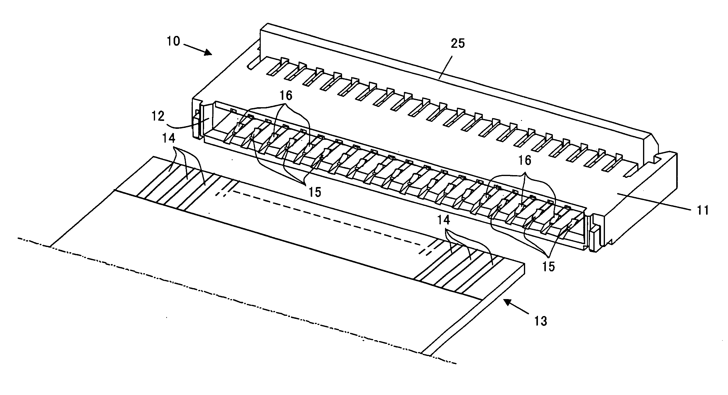
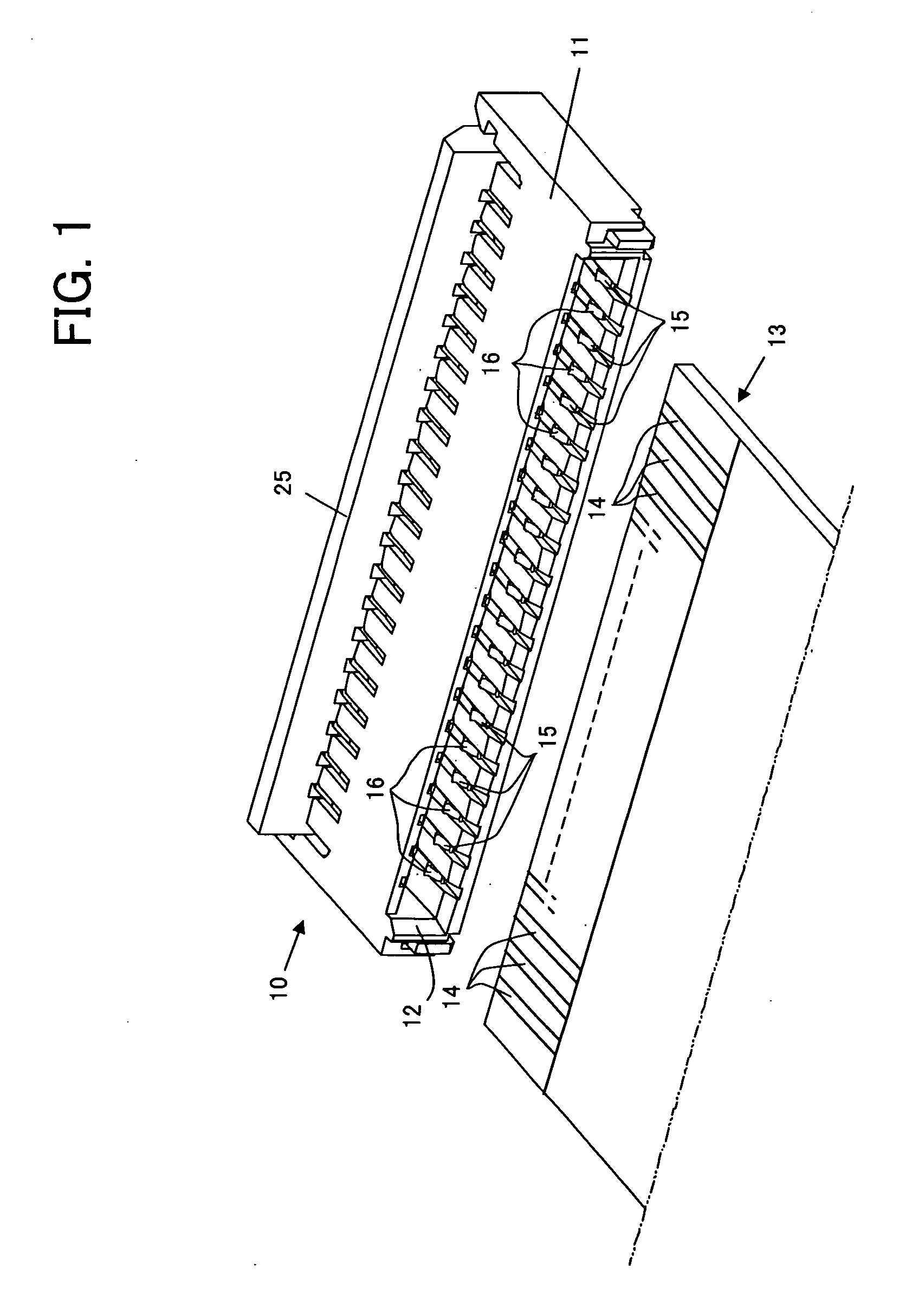
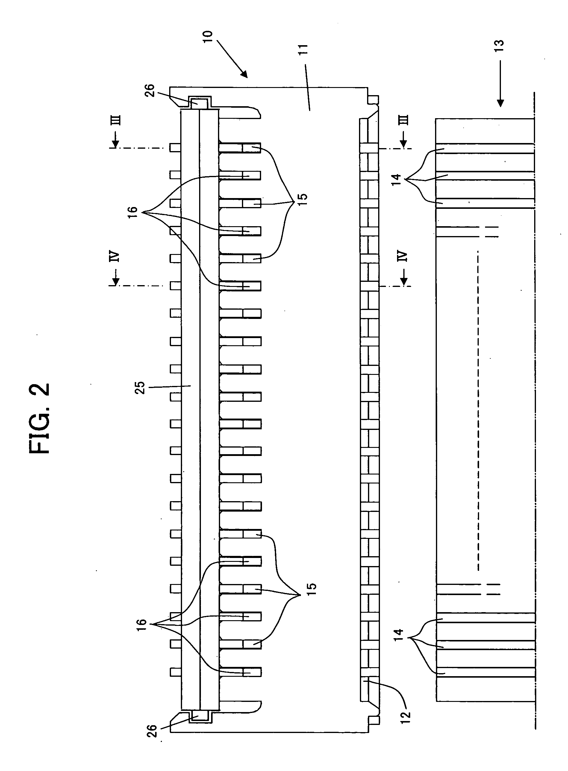
[0042] Referring to FIGS. 1 and 2, an electrical connector 10, which constitutes electrical connector according to the present invention, has a housing 11 made of insulator such as plastics or the like and provided with an opening 12 through which a circuit board is partially inserted into the housing 11. For example, a flexible printed circuit board 13 is partially inserted into the housing 11 through the opening 12. On a part of the flexible printed circuit board 13, which is inserted into the housing 11 through the opening 12, a plurality of connecting terminals 14 each made of conductive material and formed into a rectangular plate member are provided to be arranged. Each of the connecting terminals 14 is electrically connected with a conducting circuit pattern portion provided on the flexible printed circuit board 13, an illustration of which is omitted.

[0043] A plurality of conductive contacts 15 constituting first contacts and a plurality of conductive contacts 16 constitutin...

second embodiment

[0093] Although, in the above described electrical connector 30, which constitutes electrical connector according to the present invention, the conductive contacts 31 and 32 are arranged alternately in the housing 11, it is not always necessary for the electrical connector 30 according to the present invention that the conductive contacts 31 and 32 are arranged alternately in the housing 11. For example, it is possible to dispose the conductive contacts 31 at both end portions of the arrangement of the conductive contacts 31 and 32, at both end portions and a central portion of the arrangement of the conductive contacts 31 and 32, or at intervals of a predetermined number of the conductive contacts 32, so that the conductive contacts 32 are arranged between a couple of conductive contacts 31.

[0094] Further, although, in the above described electrical connector 30, which constitutes the second embodiment of electrical connector according to the present invention, two kinds of conduct...


PUM


Abstract

An electrical connector comprising a housing, first and second contacts arranged in the housing, each of which has a fixed part engaging with a board-shaped portion of the housing and an operating part movable to the fixed part, and an actuator movable to the housing for taking up first and second stations selectively, wherein each of the first and second contacts is shaped to have substantially the same space between the fixed and operating parts thereof or between the operating part thereof and the board-shaped portion of the housing when the actuator is postured to take the first station and a circuit board is not inserted into the housing, and the operating part of each of the first contacts exerts on the circuit board inserted into the housing a first temporary holding force different from a second temporary holding force exerted on the circuit board inserted into the housing by the operating part of each of the second contacts when the actuator is postured to take the first station and the circuit board is partially inserted into the housing through the opening provided thereon.

Description

BACKGROUND OF THE INVENTION [0001] 1. Field of the Invention [0002] The present invention relates generally to an electrical connector, and more particularly to an improvement in an electrical connector used for putting connecting terminals provided on a circuit board, such as a flexible printed circuit board (FPC), conductors provided in a flexible flat cable assembly (FFC) or the like in electrical connection with another electrical device, such as a main solid circuit board. [0003] 2. Description of the Prior Art [0004] In the field of electronic apparatus including various portable telephones, a relatively small-sized flexible printed circuit board or flexible flat cable assembly is often mounted on a main printed circuit board, on which various electrical parts are directly mounted, by means of an electrical connector which is fixed to and connected electrically with the main printed circuit board. The electrical connector has a plurality of conductive contacts for coming into ...

Claims


Application Information

Patent Timeline
IPC IPC(8): H01R12/00H01R12/79
CPCH01R12/88
Inventor HASHIMOTO, YOSHIMITSUTATEISHI, JINSHIMADA, YOSHINOBU
Owner DAIICHI SEIKO CO LTD
Learn More