Motorized broom

a motorized broom and broom body technology, applied in the field of brooms, can solve the problems of limiting the cleaning effect of the cleaning portion, and achieve the effect of reducing the disadvantage and/or obviating the disadvantag

Inactive Publication Date: 2007-04-05
TSAI SAM
View PDF6 Cites 16 Cited by
  • Summary
  • Abstract
  • Description
  • Claims
  • Application Information

AI Technical Summary

Benefits of technology

[0005] The present invention is to mitigate and/or

Problems solved by technology

However, the cleaning portion is fixed on the handle so that the angle and position of the cleaning portion cannot be adjusted to

Method used


Image

  • Motorized broom
  • Motorized broom
  • Motorized broom

Examples


Embodiment Construction

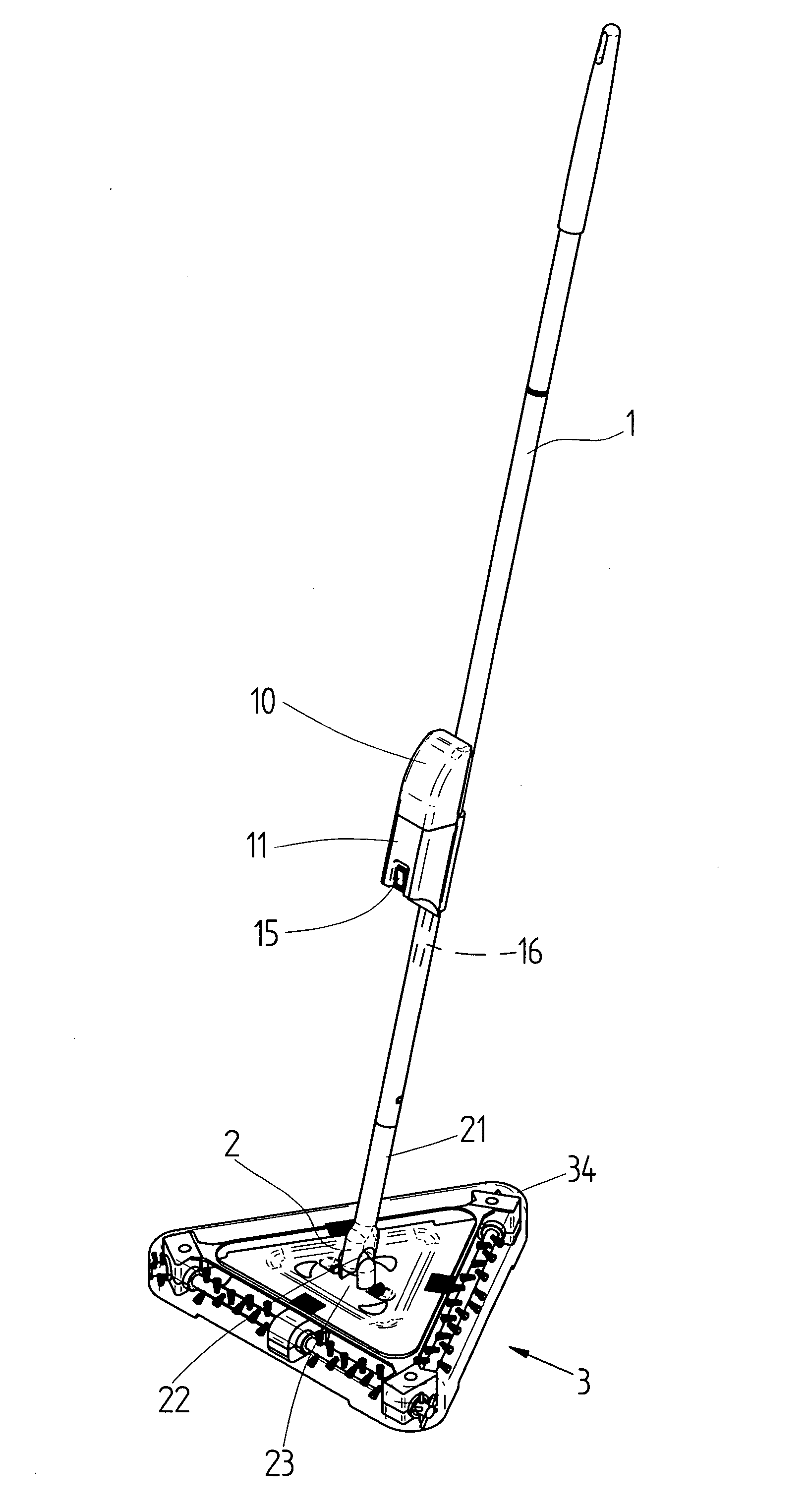
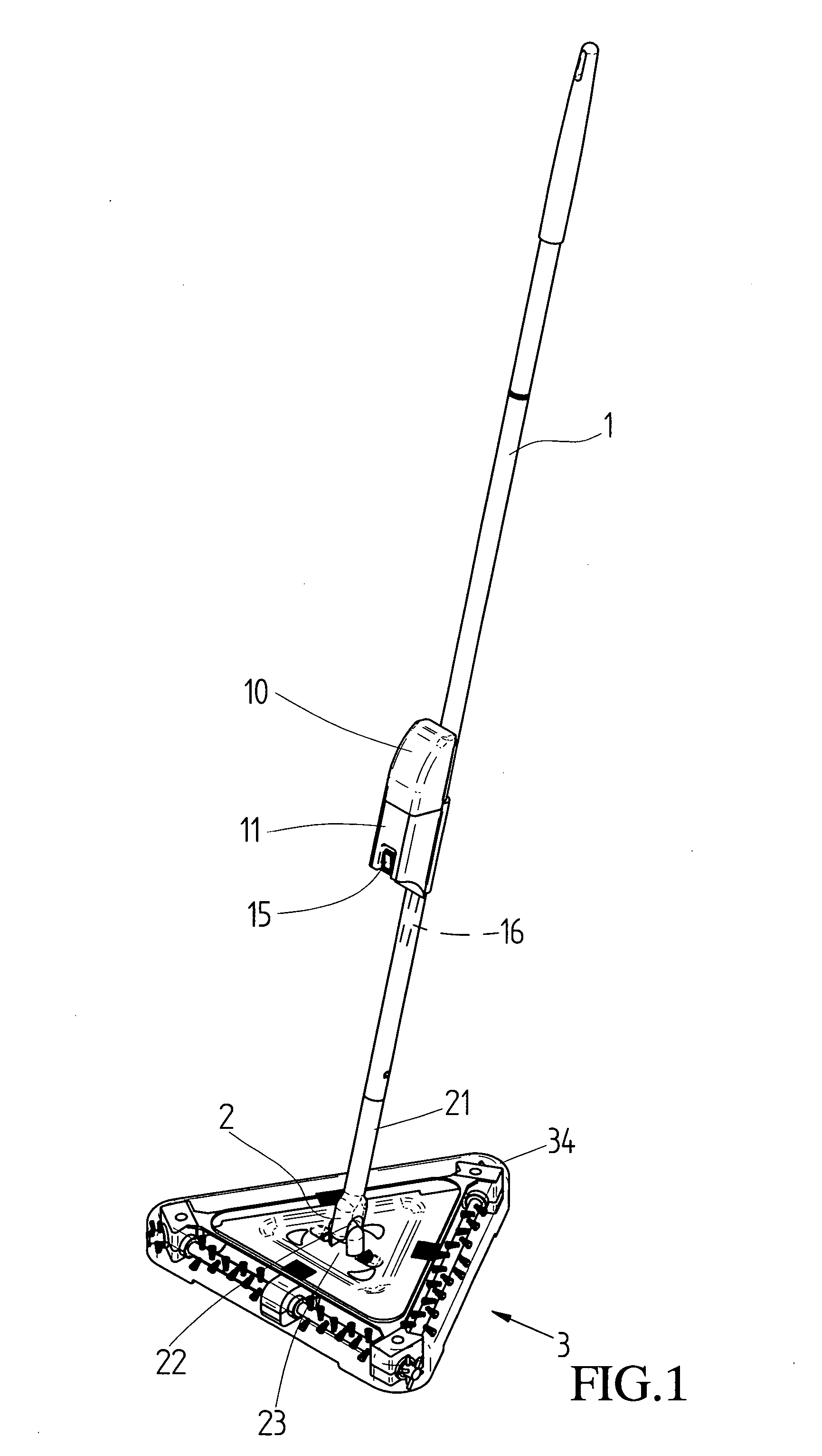
[0026] Referring to the drawings and initially to FIG. 1, a motorized broom in accordance with the preferred embodiment of the present invention comprises a handle 1, a universal connector 2, and a cleaning portion 3. The handle 1 is provided with a mounting seat 11 and a chargeable battery 10 removably mounted on the mounting seat 11.

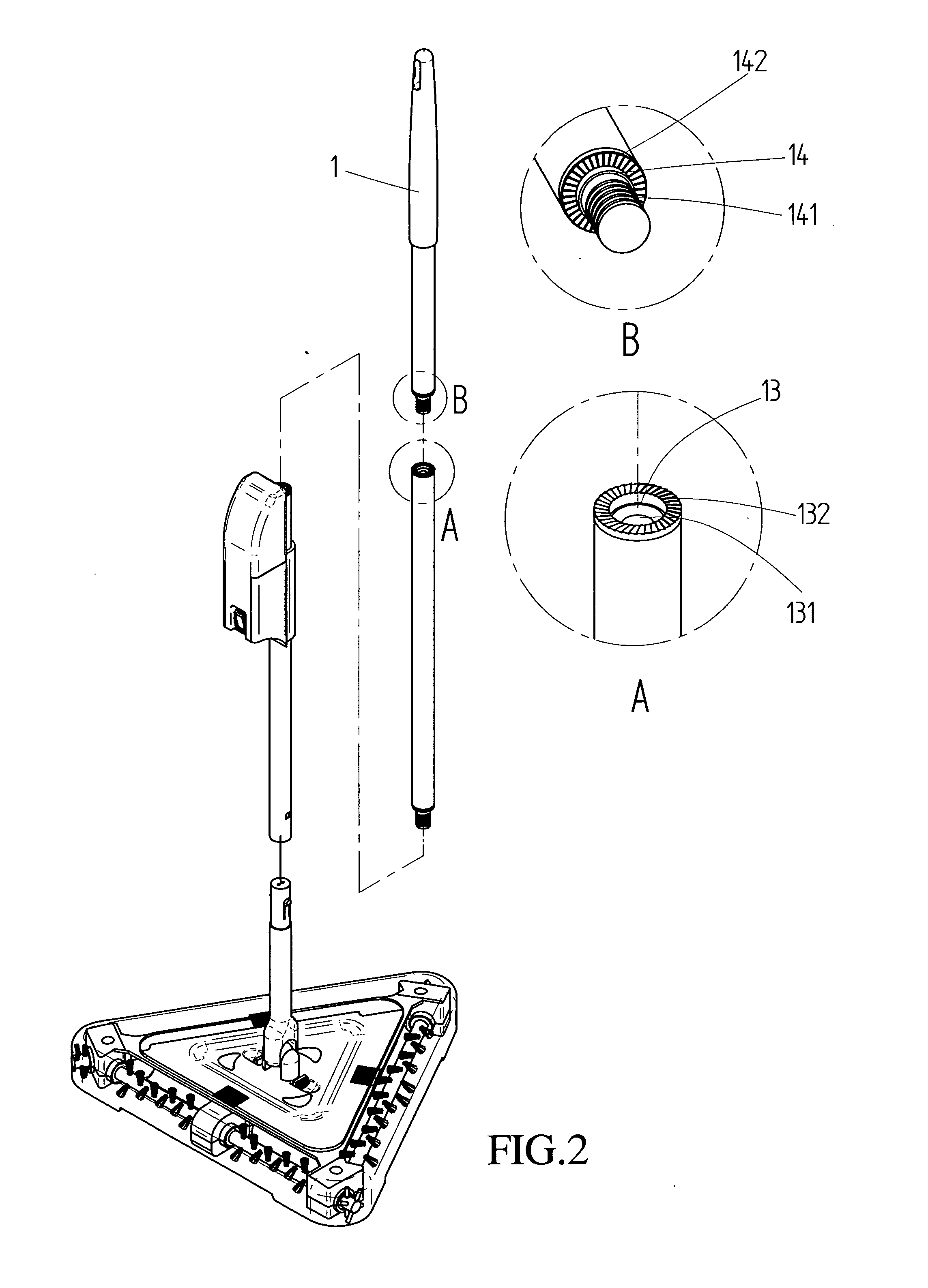
[0027] Referring to FIGS. 1 and 2, the handle 1 has a multi-stage structure and includes multiple sub-handles, wherein one sub-handle has an end provided with a stepped hole 13, a screw bore 131 and multiple protruding teeth 132, and another adjacent sub-handle has an end provided with a stepped post 14 inserted into the stepped hole 13, an outer thread 141 screwed into the screw bore 131 and multiple serrated grooves 142 engaged with the protruding teeth 132. Thus, the sub-handles of the handle 1 are combined with each other.

[0028] Referring to FIGS. 1 and 3, the universal connector 2 connects the handle 1 and the cleaning portion 3 to universally a...


PUM


Abstract

A motorized broom includes a handle, a universal connector, and a cleaning portion. The universal connector is used for connecting the handle and the cleaning portion. Thus, the universal connector together with the handle is rotatable relative to the cleaning portion universally, so that the cleaning portion is angle adjustable so as to clean the corner of the house exactly. In addition, the dust collector is removably mounted on the main base, so that the dust collector can be removed from the main base easily and rapidly, thereby facilitating a user removing the dust collector.

Description

BACKGROUND OF THE INVENTION [0001] 1. Field of the Invention [0002] The present invention relates to a broom, and more particularly to a motorized broom. [0003] 2. Description of the Related Art [0004] A conventional broom comprises a handle, a cleaning portion mounted on the lower end of the handle, and multiple bristles mounted on the cleaning portion. However, the cleaning portion is fixed on the handle so that the angle and position of the cleaning portion cannot be adjusted to fit the corresponding angle and position of the corner of the house, thereby limiting the cleaning effect of the cleaning portion. SUMMARY OF THE INVENTION [0005] The present invention is to mitigate and / or obviate the disadvantage of the conventional broom. [0006] The primary objective of the present invention is to provide a motorized broom that is angle adjustable. [0007] Another objective of the present invention is to provide a motorized broom, wherein the universal connector together with the handle...

Claims


Application Information

Patent Timeline
IPC IPC(8): A47L11/32
CPCA46B5/0033A46B5/0058A46B7/10A46B13/02A46B2200/302A47L11/32A47L11/33A47L11/4005A47L11/4013A47L11/4025A47L11/4041A47L11/4069A47L11/4075B25G1/04
Inventor TSAI, SAM
Owner TSAI SAM
Why Eureka
Try Eureka