Drum type washing machine

a drum type and washing machine technology, applied in the direction of washing machines with receptacles, other washing machines, papermaking, etc., can solve the problems of inability to smoothly perform the process of fastening the stator b>6/b> to the tub b>2/b>, energy loss or severe noise in the transmission process of driving power, etc., to achieve simple production process, prevent the damage of the fastening portion between the stator and the tub

Active Publication Date: 2007-04-05
LG ELECTRONICS INC
View PDF4 Cites 18 Cited by
  • Summary
  • Abstract
  • Description
  • Claims
  • Application Information

AI Technical Summary

Benefits of technology

[0045] First, since the supporting part is additionally provided on the rear wall of the tub, the fastening position of the stator can be determined more precisely and smoothly when assembling the stator.
[0046] Second, even when vibration is generated during the washing or spinning cycle, the damage of the fastening portion between the stator and the tub can be prevented.
[0047] Finally, since the tub supporter in the prior art may be removed, the production process can be simple and production cost can be reduced.
[0048] It is to be understood that both the foregoing general description and the following detailed description of the present invention are exemplary and explanatory and are intended to provide further explanation of the invention as claimed.

Problems solved by technology

The indirect drive motor drum type washing machine may cause energy loss or severe noise in the process of transmitting the driving power, because the driving power is not directly transmitted to the drum, but indirectly transmitted to the drum via the motor pulley and the belt.
However, since in the fastening structure between the stator 6 and the tub 2 each position determination protrusion 62c is formed in a pin shape having a narrow diameter, there is a problem that the position determination protrusion 62c may be easily damaged during the assembly or the transportation thereof.
Due to the damage of the position determination protrusion 62c, the process of fastening the stator 6 to the tub 2 may not be performed smoothly.
Thus, the fastening portion between the stator 6 and the tub 2 is easily damaged due to the weight of the stator 6, vibration in high speed rotation, and shake / deformity of the rotor 5.
However, in that case, an additional assembly work for fastening the tub supporter to the tub rear wall should be added, such that a disadvantage of low productivity may be caused thereby.

Method used


Image

  • Drum type washing machine
  • Drum type washing machine
  • Drum type washing machine

Examples


first embodiment

[0116] A process of fastening the motor to the tub 200 of the drum type washing machine having the above configuration will be described.

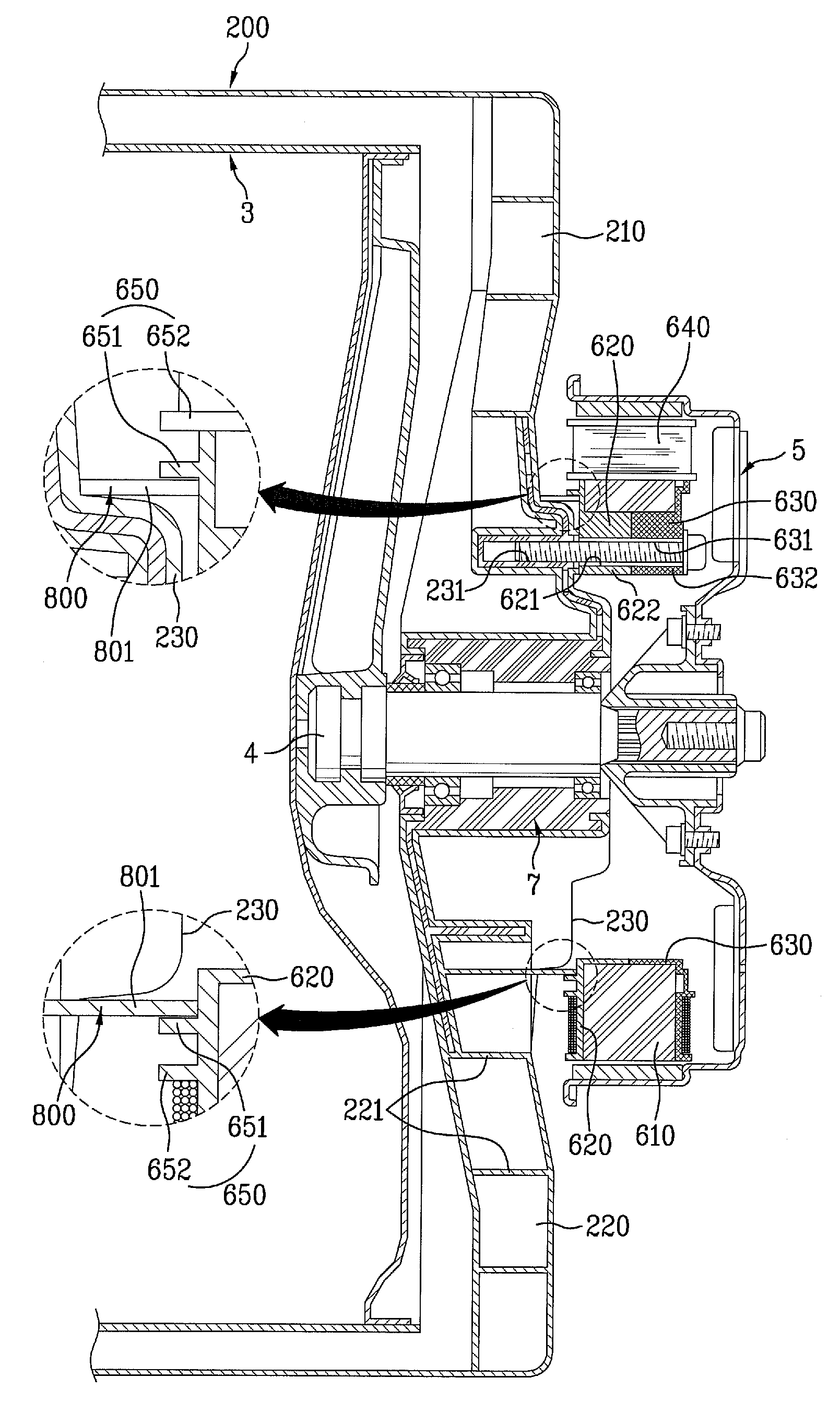
[0117] First, each position determination protrusion 623 of the first insulator 620 provided in the stator 600 is correspondingly fastened to each position determination groove 232 of the fastening part 230 formed on the rear wall of the tub 200.

[0118] In that case, each supporting rib 801 formed on the non-step part 220 of the tub 200 is arranged inside of the partition rib 651 formed on the front surface of the first insulator 620. Hence, the first fastening hole 231 of the fastening part 230 is corresponding to the second fastening hole 621 and 631 formed each projection 622 and 632 of the stator 600.

[0119] At that time, each supporting rib 801 supports the inner wall of the partition wall 651. Thus, even though the stator 600 moves down due to the load thereof during the fastening the stator 600 to the tub 200, the damage of the position det...

second embodiment

[0122] Referring to FIGS. 10 to 14, the present invention will be described. In this embodiment, the same elements as above described embodiment are denoted by the same reference numerals and description thereof will be omitted.

[0123] In the second embodiment, a supporting part 800 supports a stator rib 650, too. More specifically, the supporting part 800 includes a supporting rib 801 to support a partition rib 651 formed on the first insulator 620, specifically an inner wall of the partition rib 651, as shown in FIGS. 10 to 12.

[0124] Unlike the first embodiment, the supporting rib 801 of this embodiment may be provided on a surface bent from the step part 210 out of surfaces of the fastening part 230 formed in the tub 200. That is, the supporting rib 801 is formed on the step part 210.

[0125] The right-and-left direction width of each supporting rib 801 may be determined to correspond the first fastening hole 231 to the second fastening hole 621 and 631, which means the fastening ...

third embodiment

[0130] Referring to FIG. 15, the present invention will be described.

[0131] Much part of this embodiment is similar to the second embodiment but the fact that a supporting rib 801 has a predetermined friction power. For example, the supporting rib 801 is made of robber having compressibility to be contacted with an inner wall of a partition rib 651 formed on the stator 600, so that the partition rib 651 is supported by the supporting rib 801.

[0132] Alternatively, a sub-supporting rib 802 may be provided in this embodiment like the above embodiments.

[0133] Here, the supporting rib 801 made of robber is provided in this embodiment, because it can absorb vibration and also has less danger of damage.

[0134] In addition, a motion-proof bump 803 may be provided in an outer portion with respect to a radial direction of the supporting rib 801 to prevent the supporting rib 801 from moving. The motion-proof bump 803 prevents the stator 600 from being inclined toward any one direction, such ...


PUM


Abstract

A drum type washing machine is disclosed. The drum type washing machine of the present invention includes a tub having a fastening part formed on a rear wall thereof, a stator fastened to the fastening part of the tub, the stator having a core part having teeth formed thereon, a coil wound around each tooth, a first insulator for covering a front surface of the core part and a second insulator for covering a rear surface of the core part, a rotor provided in an outer portion of the stator to be comprised in a motor together with a stator, a stator rib formed on an inner front surface of the first insulator with respect to the radial direction of the portion of the first insulator where the coil is wound, and a supporting part provided on a rear wall of the tub to support the stator rib when the stator is fastening to the fastening part of the tub.

Description

[0001] This application claims the benefit of the Patent Korean Application Nos. 10-2005-0092367, 10-2005-0092368, 10-2005-0092369, 10-2005-0092370, and 10-2005-0092371 filed on Sep. 30, 2005, which are hereby incorporated by reference as if fully set forth herein. BACKGROUND OF THE INVENTION [0002] 1. Field of the Invention [0003] The present invention relates to a drum type washing machine, more particularly, to a drum type washing machine having an improved structure of a driving part. [0004] 2. Discussion of the Related Art [0005] In general, a drum type washing machine is classified into an indirect drive motor drum type washing machine and a direct drive motor drum type washing machine. In the indirect drive motor drum type washing machine, driving power of a motor is indirectly transmitted to a drum via a motor pulley and a belt wound around a drum pulley. Whereas, in the direct drive motor drum type washing machine, a rotor of a BLDC motor (Brushless DC motor) is directly co...

Claims


Application Information

Patent Timeline
Patent Type & Authority Applications(United States)
IPC IPC(8): D06F37/00D06F23/00
CPCD06F37/20D06F37/206D06F37/264D06F37/304
Inventor KIM, SOO BONG
Owner LG ELECTRONICS INC
Why Eureka
Try Eureka