Vibration-type measuring sensor

a technology of vibration-type measuring and pickup, which is applied in the direction of direct mass flowmeters, liquid/fluent solid measurement, volume measurement, etc., can solve the problems of high manufacturing cost, inability to practicably realize the manufacture of metal caps by means of deep drawing dies specially sized for individual nominal sizes, etc., and achieves the reduction of manufacturing cost and the cost of the deep drawing die for the metal caps.

Inactive Publication Date: 2007-04-05
ENDRESS HAUSER FLOWTEC AG
View PDF8 Cites 4 Cited by
  • Summary
  • Abstract
  • Description
  • Claims
  • Application Information

AI Technical Summary

Benefits of technology

[0073] An advantage of the invention is that, although by going back to the two cap halves (known per se) a connecting seam becomes necessary between them, the costs of the deep drawing die for the metal cap are reduced to the smaller manufacturing costs of the cap halves.
[0074] The invention will now be explained in greater detail on the basis of the figures of the drawing showing a preferred example of an embodiment. Functionally equivalent parts are given the same reference characters throughout the figures. However, reference characters are only repeated in subsequent figures to the extent such is helpful.

Problems solved by technology

The deep drawing of shaped bodies of metal, including also the above-mentioned metal caps, is done in a corresponding metal deep-drawing die, the manufacturing costs of which are very high.
However, if, for certain nominal sizes, especially for nominal sizes greater than 100 mm, but even for non-standard nominal sizes less than 100 mm, only smaller production quantities are expected, then the manufacture of the metal caps by means of such deep drawing dies specially sized for the individual nominal sizes cannot be practically realized, because of the high costs.

Method used


Image

  • Vibration-type measuring sensor
  • Vibration-type measuring sensor
  • Vibration-type measuring sensor

Examples


Embodiment Construction

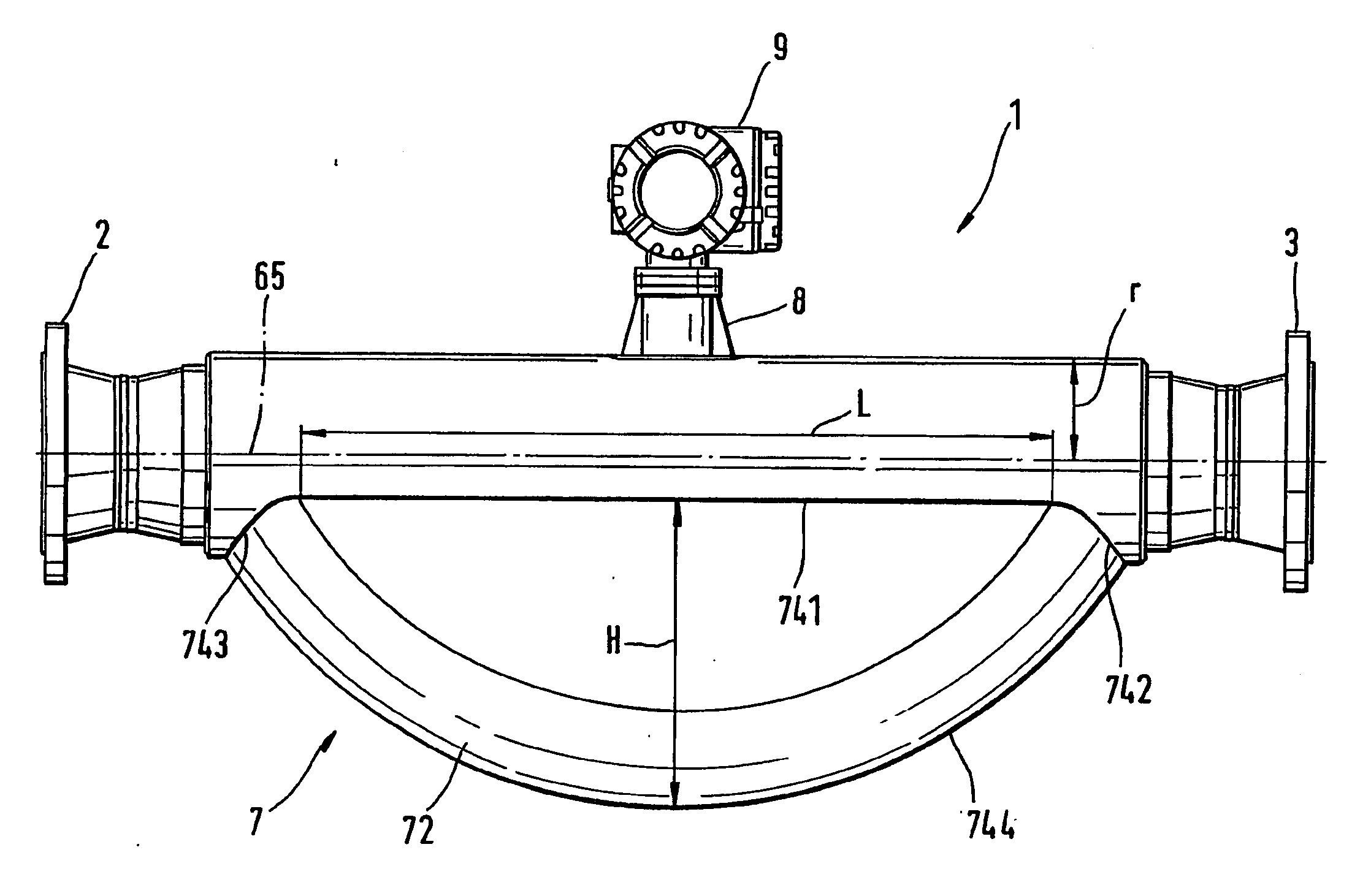
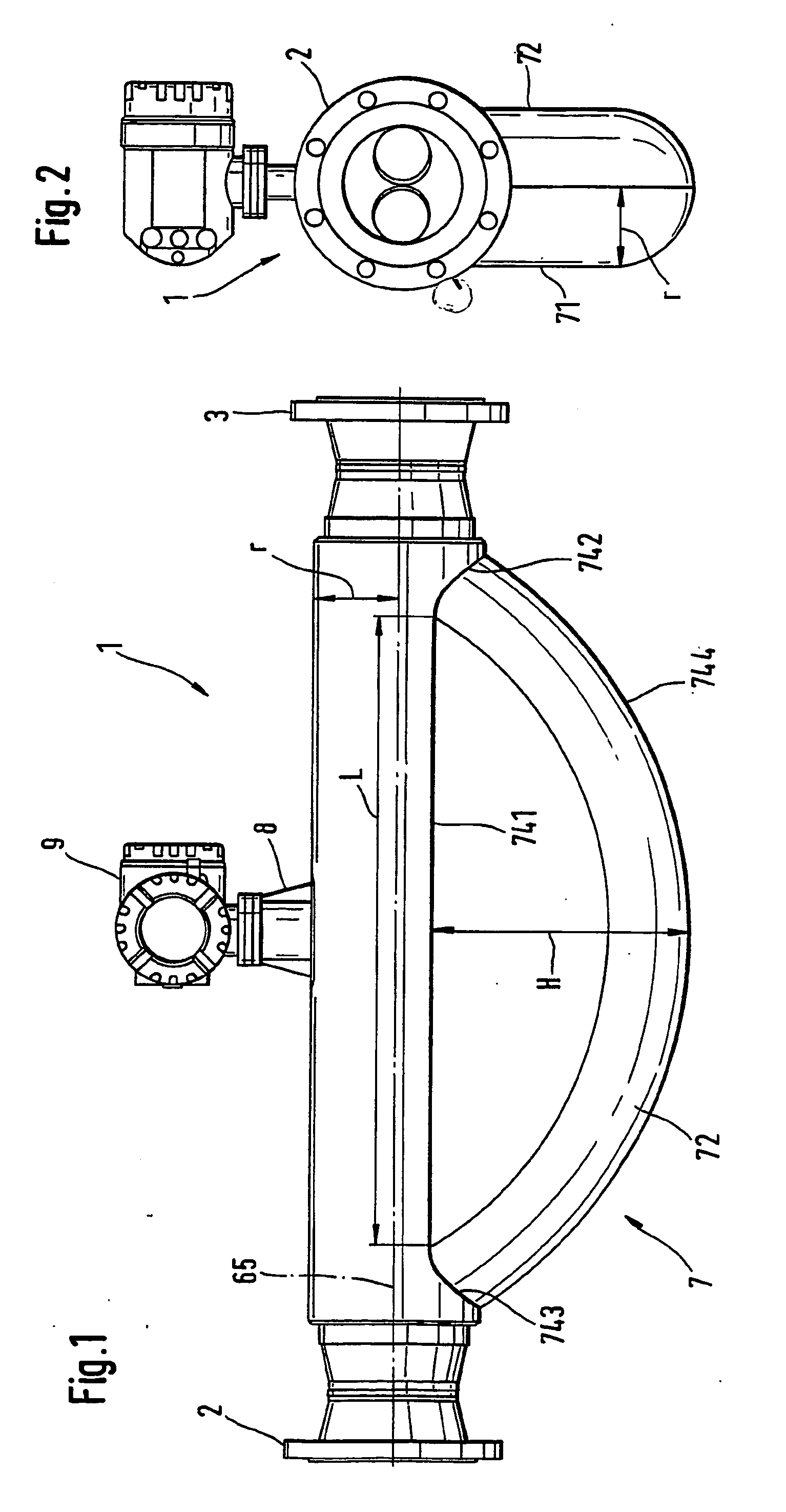
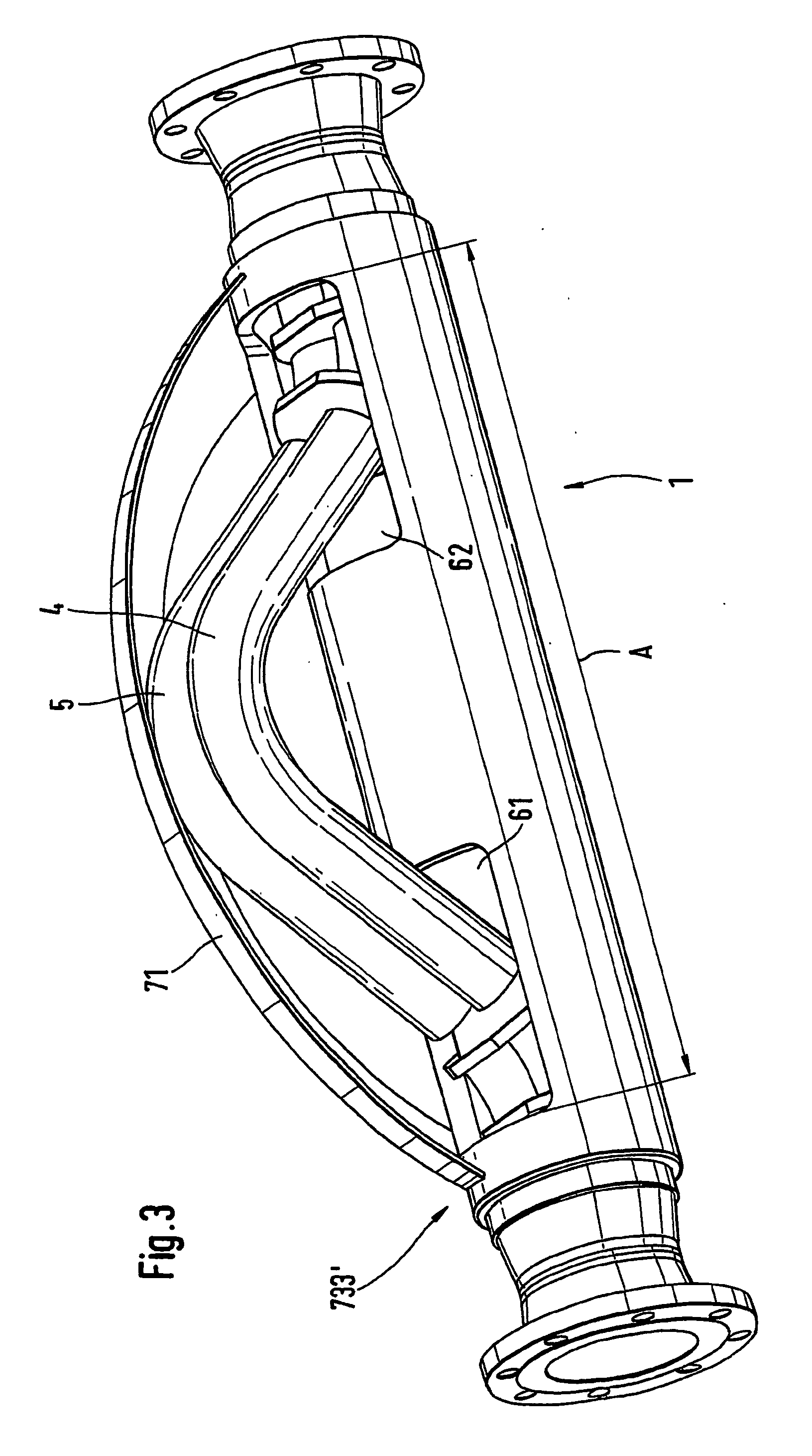
[0081] FIGS. 1 to 4 show a vibration-type sensor 1, here a Coriolis flow / density / viscosity sensor, in various views, with FIG. 1 being a side view of the measuring sensor 1, FIG. 2 its front view, and FIGS. 3 and 4 perspective views of the sensor 1 from two different viewing angles. FIGS. 1 to 4 are explained as a group in the following.

[0082] Sensor 1 is connected by way of flanges 2, 3 into the course of a pipeline of a given diameter, containing a liquid, gaseous or vaporous fluid to be measured flowing therethrough. For reasons of clarity, the pipeline is not shown here. Instead of flanges, the sensor 1 can also be connected into the pipeline by other known means, such as e.g. Triclamp connectors or screw connections.

[0083] The sensor has two parallel measuring tubes 4, 5 for guiding the fluid, which are each curved in a plane; it is also feasible to use only a single measuring tube, or at least one measuring tube curved in a screw shape can be provided.

[0084] The measuring t...


PUM

PropertyMeasurementUnit
temperaturesaaaaaaaaaa
sizeaaaaaaaaaa
sizesaaaaaaaaaa

Abstract

This sensor, for a fluid and suitable for use in a pipeline at least temporarily containing the fluid flowing therethrough, has at least one curved measuring tube, which vibrates during operation and guides the fluid, and a housing enclosing the measuring tube. The housing is composed of a metal cap of two cap halves and a supporting tube, in which the measuring tube is held at its inlet and outlet ends in a manner such that the tube can oscillate, and out of which a measuring tube segment protrudes sideways. Each cap half has an edge with, in each case, four edge portions. The edge portions are straight, the edge portions are curved, and the edge portions have the shape of circular arcs. The edge portions are welded continuously to the supporting tube and the edge portions are welded continuously to one another. The cap halves are cut out of a dish-shaped intermediate having a formed, surrounding edge bead, provided with the shape of a quarter-torus by metal spinning.

Description

[0001] This application is a divisional of U.S. patent application Ser. No. 10 / 504,075, which was filed on Aug. 9, 2004; which is a 371 of PCT / EP02 / 09211 filed on Aug. 17, 2002.FIELD OF THE INVENTION [0002] The invention relates to a vibration-type measuring pickup or sensor for a fluid to be measured. The sensor is suitable for installation in a pipeline at least temporarily containing fluid flowing therethrough. BACKGROUND OF THE INVENTION [0003] Such sensors usually include at least one curved measuring tube for guiding the fluid and at least one housing surrounding the measuring tube. The measuring tube vibrates during operation. [0004] The main representatives of such sensors are mass-flow / density / viscosity sensors operating on the Coriolis principle. These sensors can not only be used to measure the instantaneous mass flow of the fluid flowing in the pipeline, but also the density of the fluid, on the basis of the instantaneous oscillation frequency of the measuring tubes, and...

Claims


Application Information

Patent Timeline
Patent Type & Authority Applications(United States)
IPC IPC(8): G01F1/84B23P9/00
CPCG01F1/8409Y10T29/49798Y10T29/49861G01F1/8477G01F15/14
Inventor BITTO, ENNIOSCHUTZE, CHRISTIAN
Owner ENDRESS HAUSER FLOWTEC AG
Why Eureka
Try Eureka