
Low profile flush mount roof rack with rotating cross rail system

Inactive Publication Date: 2007-04-05
MAGNA INTERNATIONAL INC
View PDF9 Cites 18 Cited by
  • Summary
  • Abstract
  • Description
  • Claims
  • Application Information

AI Technical Summary

Benefits of technology

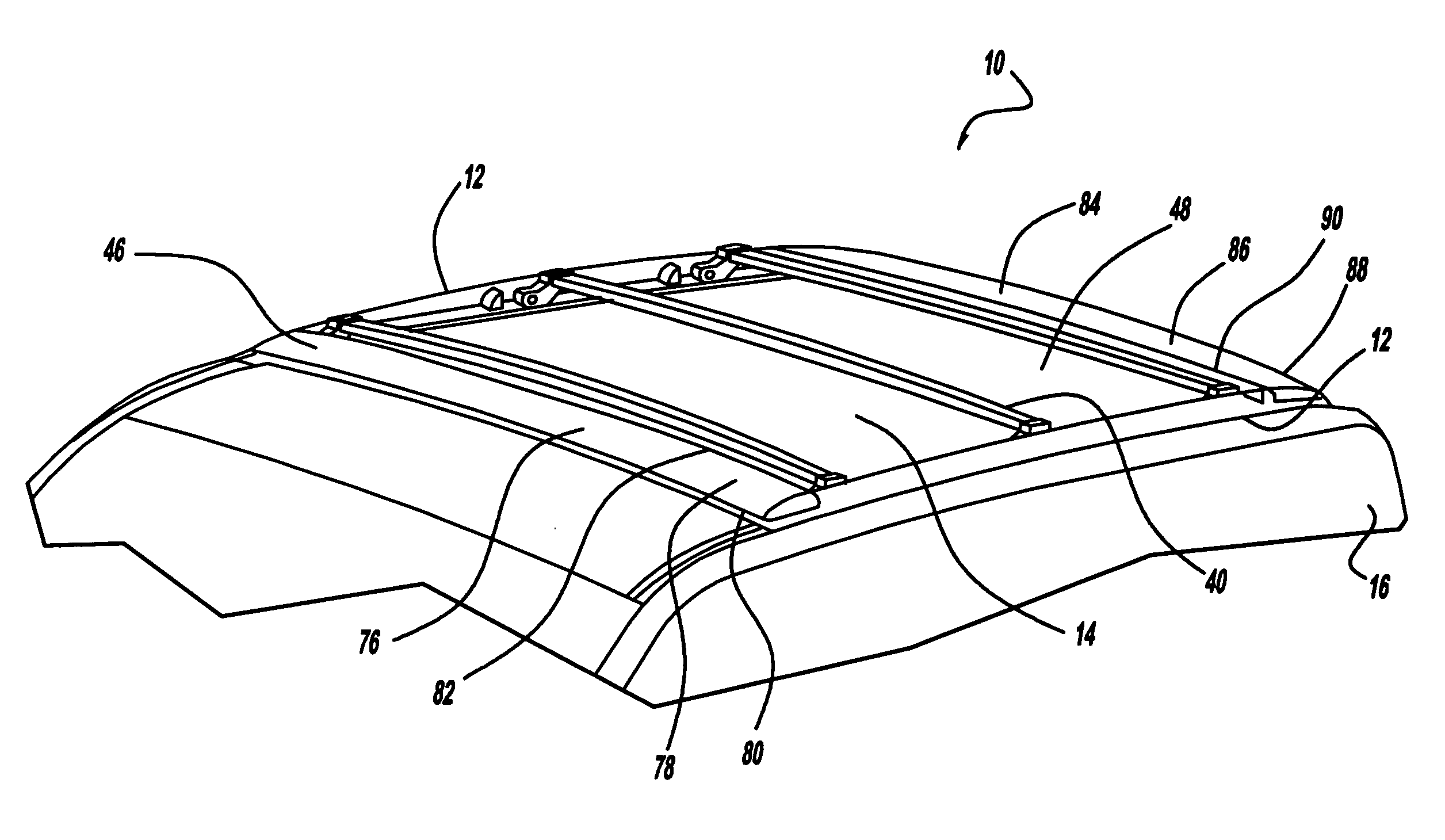
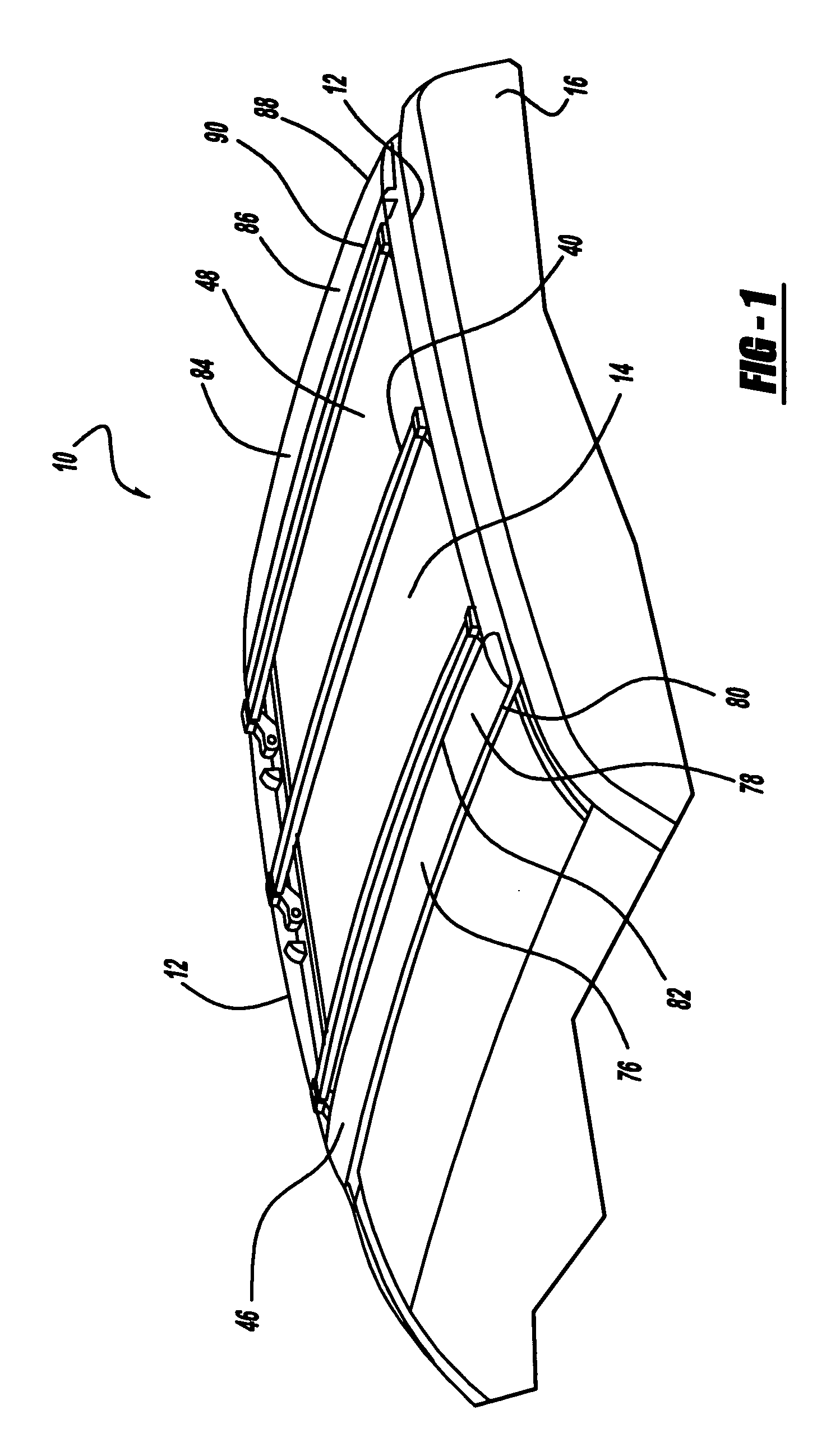
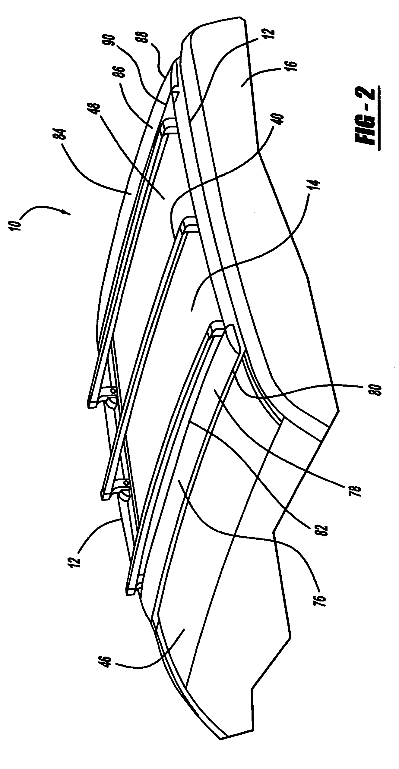
[0004] The present invention relates to a roof rack that has side rails that extend along vehicle's roof panel. The roof rack has cross rails that extend between the side rails, but the cross rails can change positions so that when they are not in use they are at a lower height then when they are in use. The cross rails are connected to a stanchion which is then connected to the side rails by a connector. The stanchion pivots about this connection point in order to alter the height of the cross rails. The side rails have a stanchion stopper which is positioned adjacent to the stanchion in order to prevent over rotation of the stanchion. For example, if the vehicle is required to make a sudden stop the momentum of the items being stored on the roof rack may apply a force to the stanchion that would result in over rotation of the stanchion. Over rotation of the stanchion could cause damage to the vehicle's roof panel and possibly to other parts of the vehicle and the items being stored on the roof rack. Therefore, the stanchion stopper prevents stanchion from rotating in an undesirable direction at undesirable times.
[0005] The side rails have angled exterior surfaces so that the side rails blend with the vehicle's roof line in order for the roof rack to be less conspicuous. In addition, the roof rack has front and rear air dams which have angled surfaces that face opposite each other. Thus, the front air dam's angled surface faces the front of the vehicle and the rear air dam's angled surface faces the rear of the vehicle. However, both the front and rear air dams decrease the amount of wind resistance caused by the roof rack which increases the fuel efficiency of the vehicle and reduces the noise caused by the vehicle's wind stream over the roof panel. In addition, the angled surfaces of the front and rear air dams have an aesthetic function. Since the bases of the angled surfaces start at the roof panel and the tops of the angled surfaces extend to the tops of the side rails the angled surfaces disguise the roof rack. Thus, the aesthetic design of the vehicle is improved as well.

Problems solved by technology

For example, if the vehicle is required to make a sudden stop the momentum of the items being stored on the roof rack may apply a force to the stanchion that would result in over rotation of the stanchion.
Over rotation of the stanchion could cause damage to the vehicle's roof panel and possibly to other parts of the vehicle and the items being stored on the roof rack.
However, both the front and rear air dams decrease the amount of wind resistance caused by the roof rack which increases the fuel efficiency of the vehicle and reduces the noise caused by the vehicle's wind stream over the roof panel.

Method used


Image

  • Low profile flush mount roof rack with rotating cross rail system
  • Low profile flush mount roof rack with rotating cross rail system
  • Low profile flush mount roof rack with rotating cross rail system

Examples


Embodiment Construction

[0013] The following description of the preferred embodiment(s) is merely exemplary in nature and is in no way intended to limit the invention, its application, or uses.

[0014] Referring to FIGS. 1 and 2 a roof rack 10 is shown. FIG. 1 depicts the roof rack 10 in its first position, or resting position, and FIG. 2 depicts the roof rack 10 in its second position, or deployed position. The roof rack 10 has side rails 12 which extend along the vehicle's roof panel 14. It is preferred that the roof rack 10 has two side rails 12 that extend parallel to the vehicle's sides 16. A gasket 18 can be placed between the roof panel 14 and the side rails 12. A gasket 18 is used in order to provide a mounting surface for the side rails 12 so that the base 20 of the side rails 12 will not damage the roof panel's 14 paint or cause structural damage to the roof panel 14. However, using a gasket 18 is optional. One factor of consideration when determining if a gasket 18 should be used is the material ...


PUM


Abstract

The present invention relates to a roof rack that provides side rails which extend along the vehicle's roof panel. The roof rack has cross rails that extend between the side rails, but the cross rails can change positions so that when they are not in use they are at a lower height then when they are in use. The cross rails are connected to a stanchion which is then connected to the side rails by a connector. The stanchion pivots about this connection point in order to alter the height of the cross rails. The side rails have a stanchion stopper which is positioned adjacent to the stanchion in order to prevent over rotation of the stanchion.

Description

FIELD OF THE INVENTION [0001] The present invention relates to a low profile roof rack that has a rotating cross rail. BACKGROUND OF THE INVENTION [0002] Many vehicles, especially sport utility vehicles and mini vans, have roof racks so that items can be stored on the roof of the vehicle. Vehicles can have standard roof racks which are installed on all the vehicles of a particular model during production or add-on roof racks which are custom to the vehicle and are usually installed after the vehicle has been manufactured. Whether a vehicle has a standard roof rack or an add-on roof rack, the roof racks normally extend several inches above a vehicle's roof panel. A roof rack that extends several inches above the roof panel is undesirable because the roof rack results in additional wind resistance which can affect the fuel efficiency of the vehicle. Also, the air flow over the roof rack, especially the cross rails, can cause additional noise due to the wind stream over the vehicle, wh...

Claims


Application Information

Patent Timeline
IPC IPC(8): B60R9/00
CPCB60R9/045
Inventor STAPLETON, CRAIG ALAN
Owner MAGNA INTERNATIONAL INC
Learn More