Output driver for controlling impedance and intensity of pre-emphasis driver using mode register set

a technology of output driver and mode register, applied in the field of output driver for efficiently transmitting data, can solve the problems of affecting the efficiency of output signal matching, etc., to achieve efficient matching of output impedance

Active Publication Date: 2007-04-05
SAMSUNG ELECTRONICS CO LTD
View PDF15 Cites 17 Cited by
  • Summary
  • Abstract
  • Description
  • Claims
  • Application Information

AI Technical Summary

Benefits of technology

[0013] A feature of the present invention is to provide an output driver that can e

Problems solved by technology

If appropriate matching is not achieved, a transmission signal may be distorted.
Accordingly, the prior art output driver has a problem in that it is very difficult to match the output impedance OIM to the transmission impedance TIM of the transmission line 1 and the reception impedance RIM of

Method used


Image

  • Output driver for controlling impedance and intensity of pre-emphasis driver using mode register set
  • Output driver for controlling impedance and intensity of pre-emphasis driver using mode register set
  • Output driver for controlling impedance and intensity of pre-emphasis driver using mode register set

Examples


Embodiment Construction

[0035] The present invention will now be described in detail in connection with preferred embodiments with reference to the accompanying drawings.

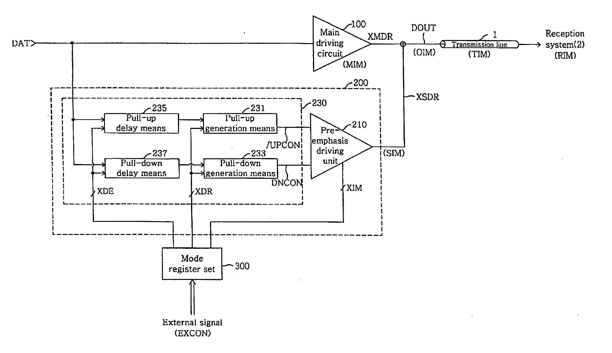
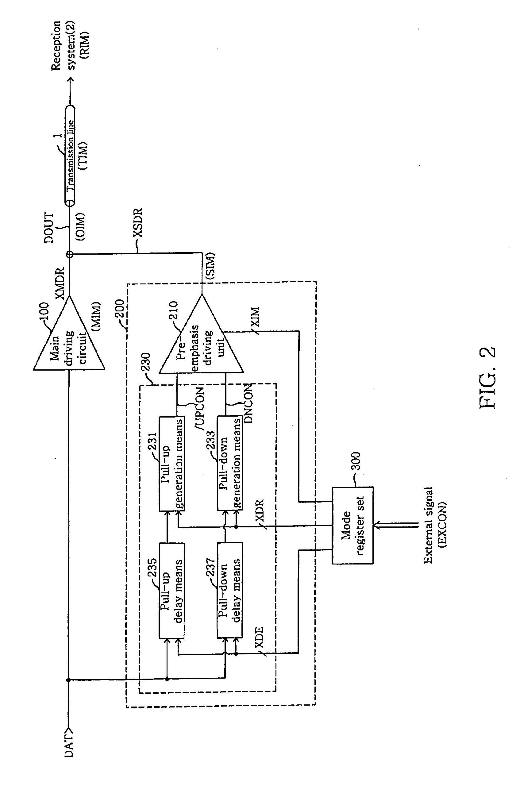
[0036]FIG. 2 is a block diagram of an output driver according to an embodiment of the present invention.

[0037] The output driver of the present invention drives an output signal DOUT at a predetermined output impedance OIM according to a received data signal DAT.

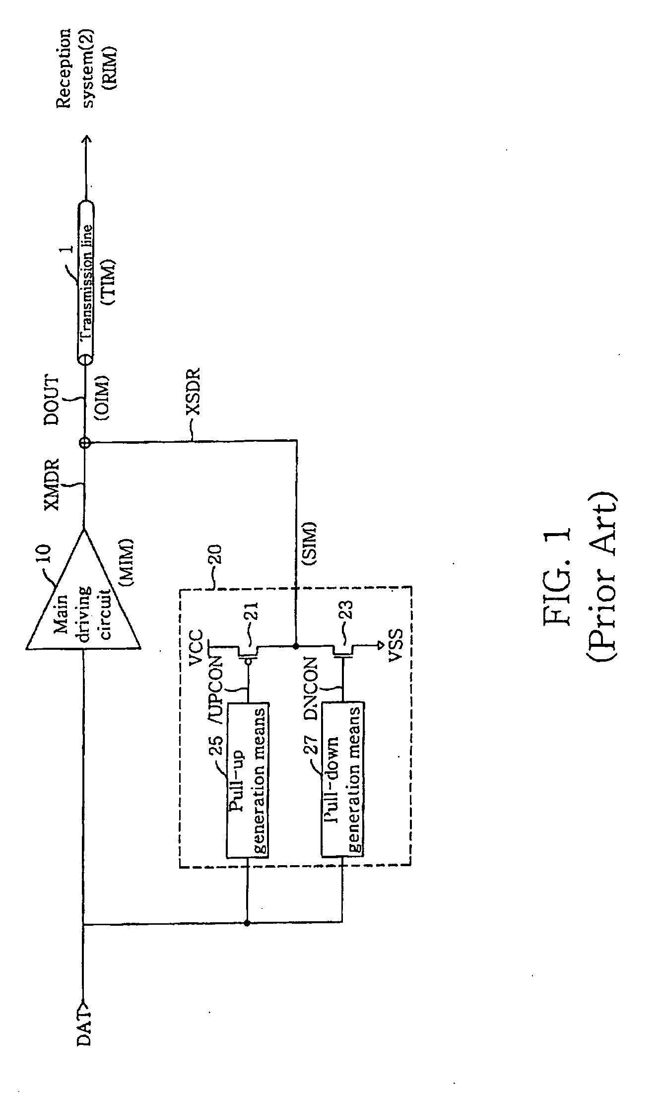
[0038] Referring to FIG. 2, the output driver of the present invention includes a main driving circuit 100, an auxiliary driving circuit 200 and a mode register set 300.

[0039] The main driving circuit 100 generates a main signal XMDR to a transmission line 1 according to the data signal DAT. Furthermore, the auxiliary driving circuit 200 generates an auxiliary signal XSDR to the transmission line 1 according to the data signal DAT. The main signal XMDR and the auxiliary signal XSDR are combined with each other and form an output signal DOUT.

[0040] In the present specification,...


PUM


Abstract

An output driver controls impedance using a mode register set. The output driver includes a main driving circuit that outputs and drives a main signal based on a data signal to a predetermined transmission line, an auxiliary driving circuit that outputs and drives an auxiliary signal to the transmission line, and a mode register set. The mode register set generates an impedance control signal group, a driving width control signal group and a delay control signal group. The amount of an auxiliary impedance (SIM), and the driving width and driving time point of an auxiliary signal (XSDR) can be controlled using the impedance control signal group, the driving width control signal group and the delay control signal group. Therefore, in accordance with the output driver of the present invention, the amount of output impedance (OIM), a pre-emphasis width and a pre-emphasis time point can be readily controlled, and the efficiency of the transmission of an output signal to a reception system is improved.

Description

RELATED APPLICATION [0001] This application relies for priority on Korean Patent Application number 10-2005-0091896, filed in the Korean Intellectual Property Office on Sep. 30, 2005, the entire contents of which are incorporated herein by reference. BACKGROUND OF THE INVENTION [0002] 1. Field of the Invention [0003] The present invention relates generally to an electronic circuit and, more particularly, to an output driver for efficiently transmitting data to a reception system. [0004] 2. Description of the Related Art [0005] A variety of signals, including data signals, are transmitted from a transmission system to a reception system via a transmission line. In general, the transmission system includes an output driver so as to efficiently transmit data. It is very important to design the output impedance of the output driver so that it has a value corresponding to the transmission impedance of the transmission line and the reception impedance of the reception system. Furthermore,...

Claims


Application Information

Patent Timeline
IPC IPC(8): H03K19/094
CPCH03K19/017545H03K19/017581H04L25/0278H04L25/0286G06F13/14
Inventor SONG, IN DALLEE, JUNG BAE
Owner SAMSUNG ELECTRONICS CO LTD
Why Eureka
Try Eureka