Method of recovering digital data from a clocked serial input signal and clocked data recovery circuit

Active Publication Date: 2007-04-05
TEXAS INSTR INC
View PDF5 Cites 11 Cited by
  • Summary
  • Abstract
  • Description
  • Claims
  • Application Information

AI Technical Summary

Benefits of technology

[0002] The present invention provides a method and a circuit for post-pr

Problems solved by technology

Due to the jitter in the received signal, however, the voting process may be

Method used


Image

  • Method of recovering digital data from a clocked serial input signal and clocked data recovery circuit
  • Method of recovering digital data from a clocked serial input signal and clocked data recovery circuit
  • Method of recovering digital data from a clocked serial input signal and clocked data recovery circuit

Examples


Example

DETAILED DESCRIPTION OF THE DRAWINGS

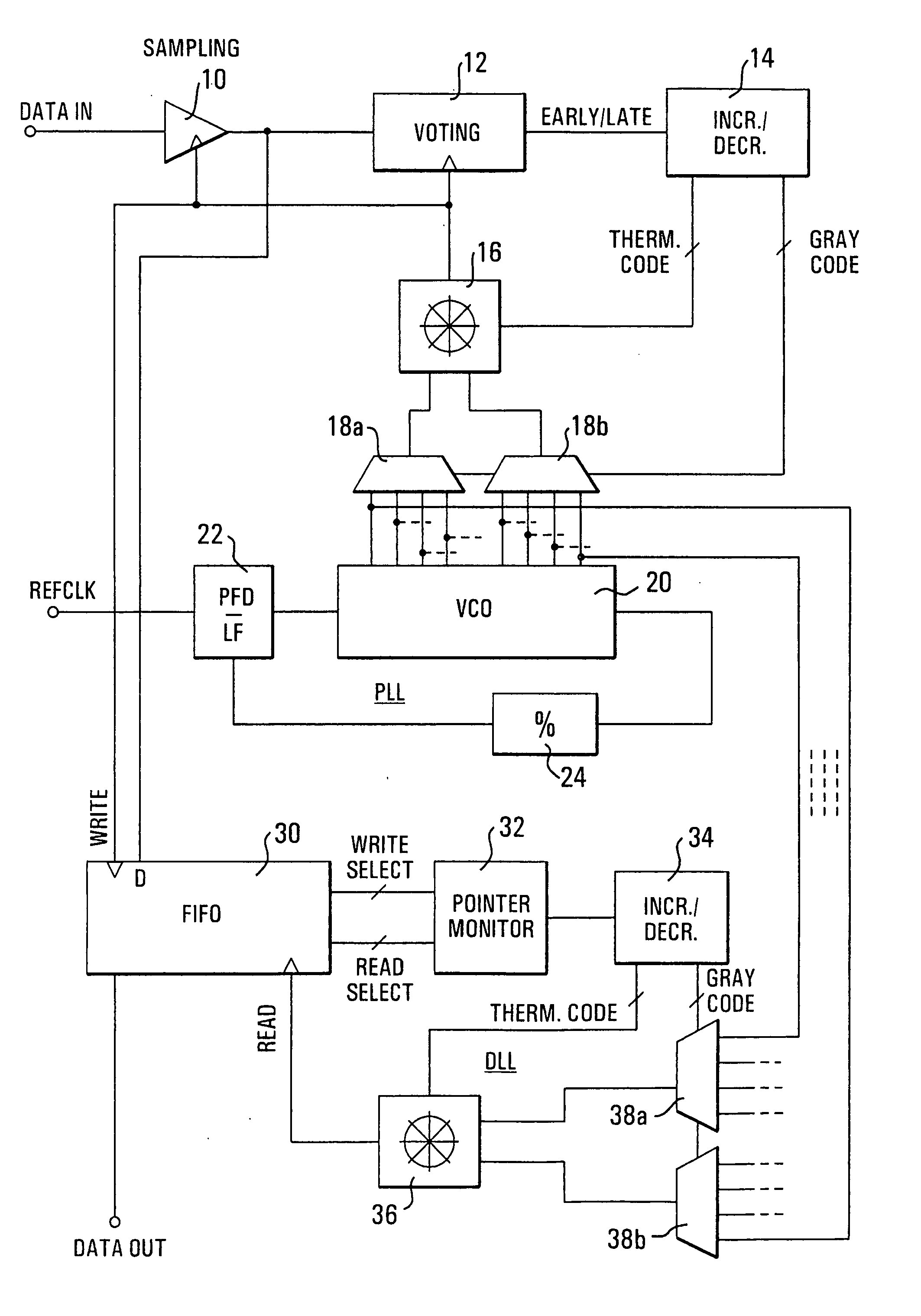
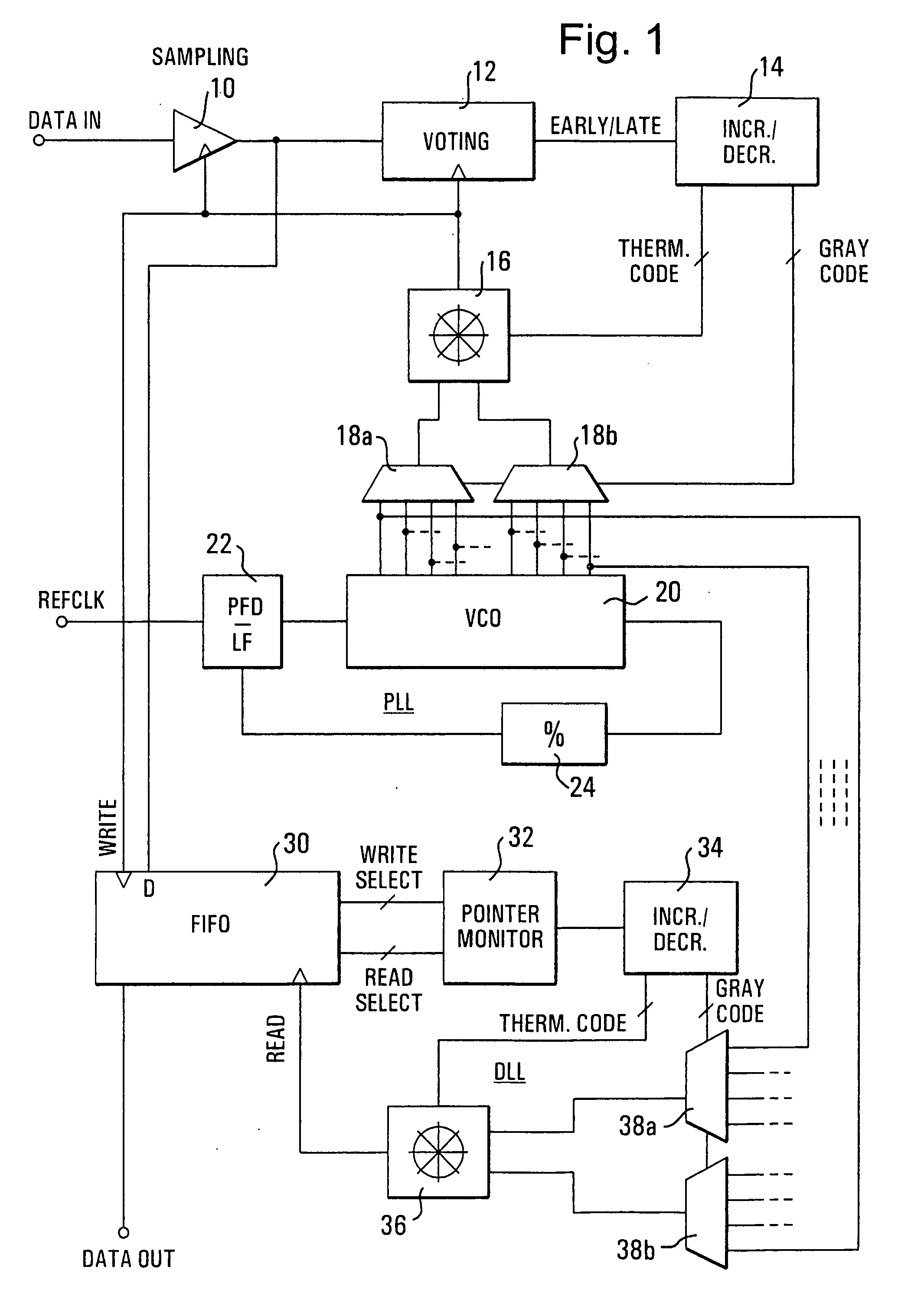
[0012] The inventive data recovery circuit in FIG. 1 is a CMOS circuit that includes a sampling circuit 10 with a signal input, a signal output and a sampling clock input. A received signal DATA IN is applied to the signal input. The signal output is connected to an input of a voting circuit 12 that has a clock input and a control output. The voting circuit 12 detects early / late conditions and provides a suitable control signal to an increment / decrement circuit 14 that has two outputs. A first one of the outputs provides a thermometer-coded control signal to a phase interpolator 16; a second one of the outputs provides a Gray-coded control signal to a multiplexer pair 18a, 18b. The phase interpolator 16 has an output connected to the clock inputs of the sampling circuit 10 and the voting circuit 12. The multiplexer pair 18a, 18b has two outputs connected to respective signal inputs of the phase interpolator 16. A phase locked loop (PLL) includes ...


PUM


Abstract

Digital data are recovered from a clocked serial input signal. The input signal is sampled with a sampling clock signal supplied by a first phase interpolator to obtain a sampled digital signal. The first phase interpolator is controlled with a voting circuit to adjust the phase of the sampling clock relative to the eye in the eye-diagram of the input signal. The first phase interpolator has signal inputs connected to signal outputs of a voltage controlled oscillator in a phase-locked loop circuit that has a reference signal input to which the reference clock signal is applied. The sampled digital signal is written to a single-bit FIFO buffer with a write clock signal that has the same timing as the sampling clock. A filtered output signal is read from the FIFO buffer with a read clock signal supplied by a second phase interpolator that has signal inputs connected to the signal outputs of the voltage controlled oscillator in the phase-locked loop. The second phase interpolator is controlled with a pointer monitor that monitors the write and read select pointers in the FIFO buffer to adjust the timing of the read clock signal relative to the write clock signal. With this method, the hunting jitter is filtered out while a frequency offset is still allowed between the reference clock and the data signal.

Description

BACKGROUND OF THE INVENTION [0001] In a digital system with serial transmission of data, a received signal may be related to a system clock of a transmitter (a “clocked signal”). The frequency of the received signal is the same as the clock frequency. In a real environment, however, the timing relation between the received signal and the system clock will vary slightly. Deviations in frequency of several hundreds of ppm will normally be observed. On the side of the receiver, these deviations, referred to as “jitter”, must be detected and compensated by sampling the received data with a clock that is adjusted in phase in an attempt to center the sampling point with respect to the eye in the eye-diagram of the input signal. The required phase adjustments to center the sampling point within the eye occur stepwise as a result of conditions determined by a voting unit. Due to the jitter in the received signal, however, the voting process may be mislead, and phase adjustments occur that a...

Claims


Application Information

Patent Timeline
IPC IPC(8): H03M7/00
CPCG06F13/4291H03L7/07H03L7/0814H03L7/0996H04L7/0025H04L7/0331H04L7/005
Inventor GOLLER, JOERGPRIEGO, ANTONIO
Owner TEXAS INSTR INC
Why Eureka
Try Eureka