
8VSB bandwidth-limited peak filter

a bandwidth-limited, peak filter technology, applied in the direction of amplitude demodulation, amplitude demodulation by homodyne/synchrodyne circuit, electrical apparatus, etc., can solve the problems of increasing the cost of output drivers, power consumption of transmitters, and little practical improvemen

Inactive Publication Date: 2007-04-05
AXCERA
View PDF10 Cites 1 Cited by
  • Summary
  • Abstract
  • Description
  • Claims
  • Application Information

AI Technical Summary

Benefits of technology

[0036] The means for filtering can utilize a square root raised cosine bandpass to filter the input signal.
[0037] The gain at the middle frequencies passable by said means for filterin...

Problems solved by technology

This can increase the cost of the output drivers and, hence, the power consumption of the transmitter, for little practical improvement.
In addition to being larger and more expensive, transmitters that utilize linear amplifiers operated at a higher peak-to-average ratios would also be less efficient.
Such a process, however, is complicated and expensive.
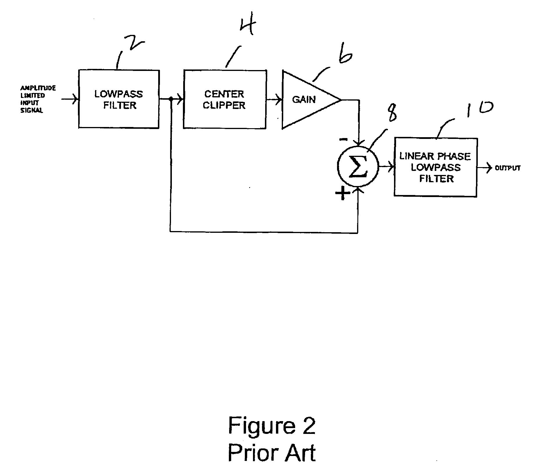
As a result, just the unwanted peaks will emerge from the center clipper.

Method used


Image

  • 8VSB bandwidth-limited peak filter
  • 8VSB bandwidth-limited peak filter
  • 8VSB bandwidth-limited peak filter

Examples


Embodiment Construction

[0042] The present invention will be described with reference to the accompanying figures where like reference numbers correspond to like elements.

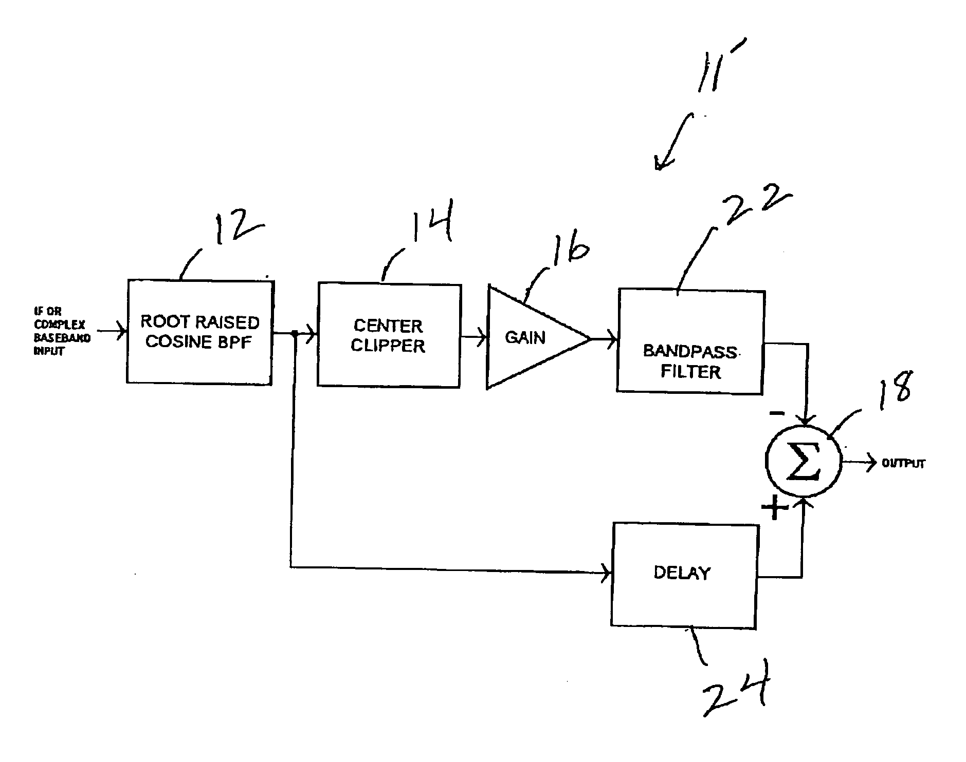
[0043] With reference to FIG. 3, the prior art method discussed above in connection with FIGS. 1 and 2 may be adapted and modified to work with 8VSB bandpass filters or baseband filters operating on complex baseband signals.

[0044] Specifically, a modulated complex baseband or IF input signal is applied to a square root raised cosine bandpass filter 12 that is part of an 8VSB filter 11 in accordance with the present invention. The gain at the middle frequencies passable by square root raised cosine bandpass filter 12 is constant. The gain at frequencies on opposites sides of the middle frequencies passable by the square root raised cosine bandpass filter (i.e., at frequencies greater than and less than said middle frequencies) can vary (decrease) according to a square root raised cosine function. Square root raised cosine bandpass filter...


PUM


Abstract

In an 8-level vestigial sideband (8VSB) filter and method, a bandpass filter processes an input signal to produce a first bandpass filtered output signal. A center clipper circuit is responsive to first and second threshold values and the first bandpass filtered output signal to produce a center clipper output signal that has (1) zero amplitude when the bandpass filtered output signal has an amplitude that is between the first and second threshold values and (2) an amplitude equal to an amplitude of the bandpass filtered output signal minus a value of one of the threshold values otherwise. A summing circuit is responsive to the combination of the center clipper output signal and the first bandpass filtered output signal to produce a summing circuit output signal. The first bandpass filter output signal is a square root raised cosine filter output signal.

Description

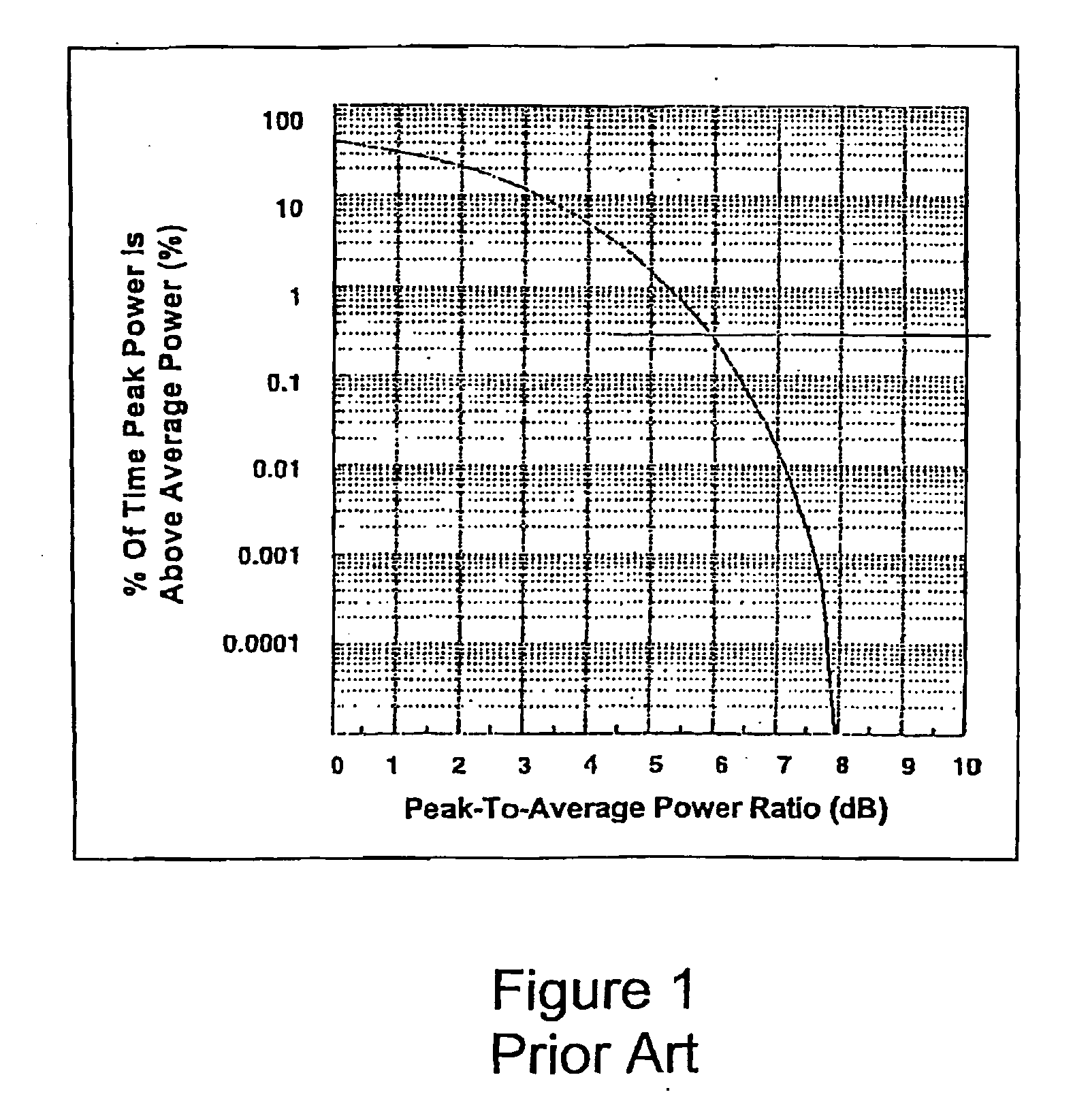
CROSS REFERENCE TO RELATED APPLICATION [0001] This application claims priority from U.S. Provisional Patent Application No. 60 / 722,194, filed Sep. 30, 2005, the contents of which are incorporated herein by reference.BACKGROUND OF THE INVENTION [0002] 1. Field of the Invention [0003] The present invention relates to an 8VSB filter for use in digital television broadcast transmitters. [0004] 2. Description of Related Art [0005] In ATSC (Advanced Television Systems Committee) 8VSB (8 level vestigial sideband) digital television broadcast transmitters, there is often a tradeoff made between transmitter output power and nonlinear distortion. [0006]FIG. 1 shows a graph of peak to average ratio versus the log10 of different probability levels. As can be seen from this graph, the peak-to-average ratio of 8VSB signals is approximately 8 dB at low probability levels (less than 0.0001%). However, the peak-to-average ratio of 8VSB signals is often described as being approximately 6 dB, as it is...

Claims


Application Information

Patent Timeline
IPC IPC(8): H03D1/24
CPCH04L27/04
Inventor HERSHBERGER, DAVID L.
Owner AXCERA
Learn More