Magnified machine vision user interface

a machine vision and user interface technology, applied in the field of machine vision inspection systems, can solve the problems of large workpieces, difficulty in “navigation” to various microscopic features to be inspected on a workpiece, and inability to distinguish between similar features, so as to facilitate navigation and/or programming, facilitate navigation and/or inspection, and improve the ease of use and gui

Active Publication Date: 2007-04-05
MITUTOYO CORP
View PDF14 Cites 39 Cited by
  • Summary
  • Abstract
  • Description
  • Claims
  • Application Information

AI Technical Summary

Benefits of technology

[0008] Currently, the users of precision machine vision inspection systems may spend a significant portion of their part-programming or manual inspection time navigating to particular features of a workpiece in order to set up appropriate video tools and adjust their parameters. In such systems, improvements in the ease-of-use and GUI features of a user interface that facilitates navigation and / or programming are desirable. The present invention is directed to novel and efficient features of a user interface that facilitates navigation and / or inspection programming related to workpiece features that are distributed beyond the limits of a single field of view of a workpiece. In various embodiments, the user interface includes controls and / or menus or windows that allow a set of individual features to be defined or identified in dependence upon a customized set of parameters. The controls and / or menus or windows and methods employed in the context of various embodiments of the user interface disclosed herein may allow a more realistic workpiece navigation image and / or allow that image to be updated with a discernibly faster and more convenient response time in response to various user inputs, in comparison to known user interfaces used for similar purposes. In addition, various aspects of the user interface may convey more specific or detailed information regarding features in the workpiece navigation image, in comparison to known user interfaces used for similar purposes, and may provide a more precise and intuitive method to isolate and identify a desired set of features for purposes of navigation and / or inspection programming operations.

Problems solved by technology

Furthermore, in industrial inspection environments, very large workpieces are common.
In such cases, “navigation” to various microscopic features to be inspected on a workpiece can be difficult, particularly when the field of view is small compared to the size or distribution of the features to be inspected, and particularly when a number of confusingly similar or identical features are included on the workpiece.
However, manual navigation may be both slow and prone to errors in distinguishing between similar features.
However, in many cases CAD data or workpiece drawings may not exist, or may be in a format that is incompatible with such user interfaces.
Also, the differences between the representation of a feature in a CAD-based user interface and the corresponding actual instance of the corresponding feature in a real workpiece image may limit the utility or application of such a CAD interface.

Method used


Image

  • Magnified machine vision user interface
  • Magnified machine vision user interface
  • Magnified machine vision user interface

Examples


Embodiment Construction

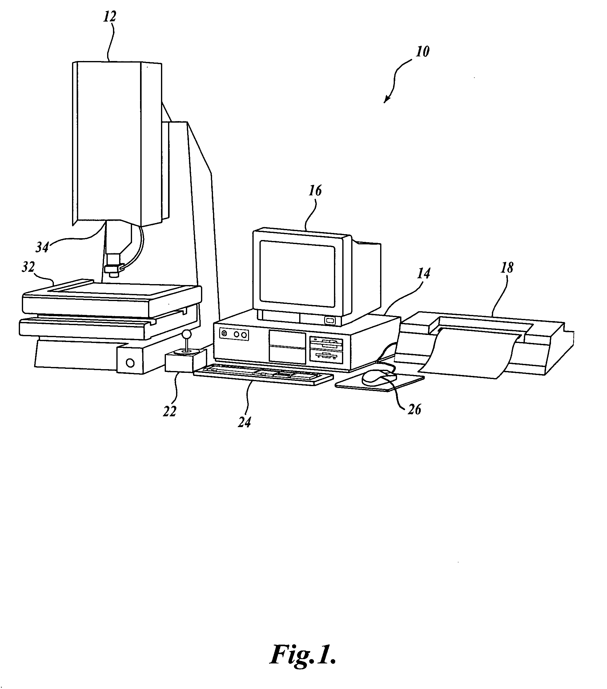
[0023]FIG. 1 is a block diagram of one exemplary machine vision inspection system 10 usable in accordance with the present invention. The machine vision inspection system 10 includes a vision measuring machine 12 that is operably connected to exchange data and control signals with a controlling computer system 14. The controlling computer system 14 is further operably connected to exchange data and control signals with a monitor or display 16, a printer 18, a joystick 22, a keyboard 24, and a mouse 26. The monitor or display 16 may display a user interface suitable for controlling and / or programming the operations of the machine vision inspection system 10. In various embodiments, an additional monitor or display (not shown) similar to the monitor or display 16 may be included, and the user interface may be displayed on either or both monitors or displays.

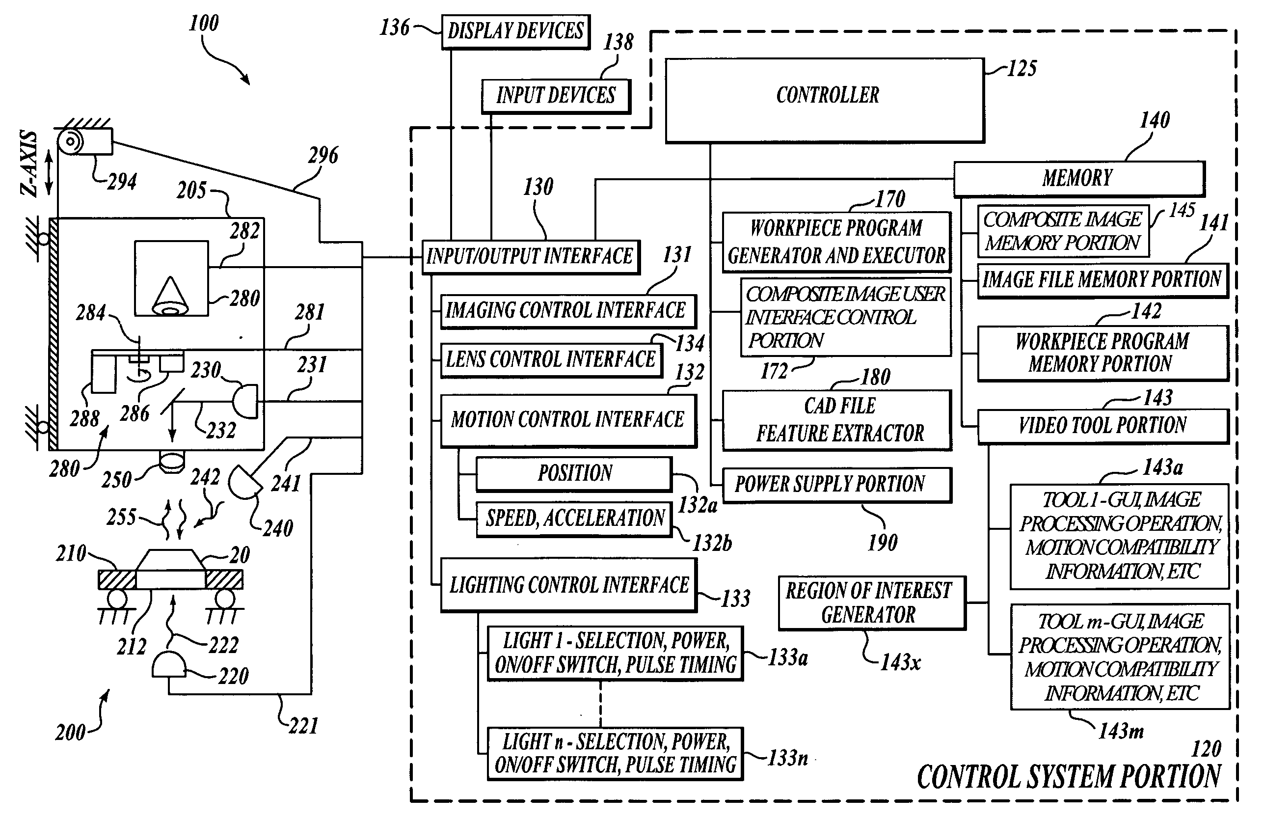
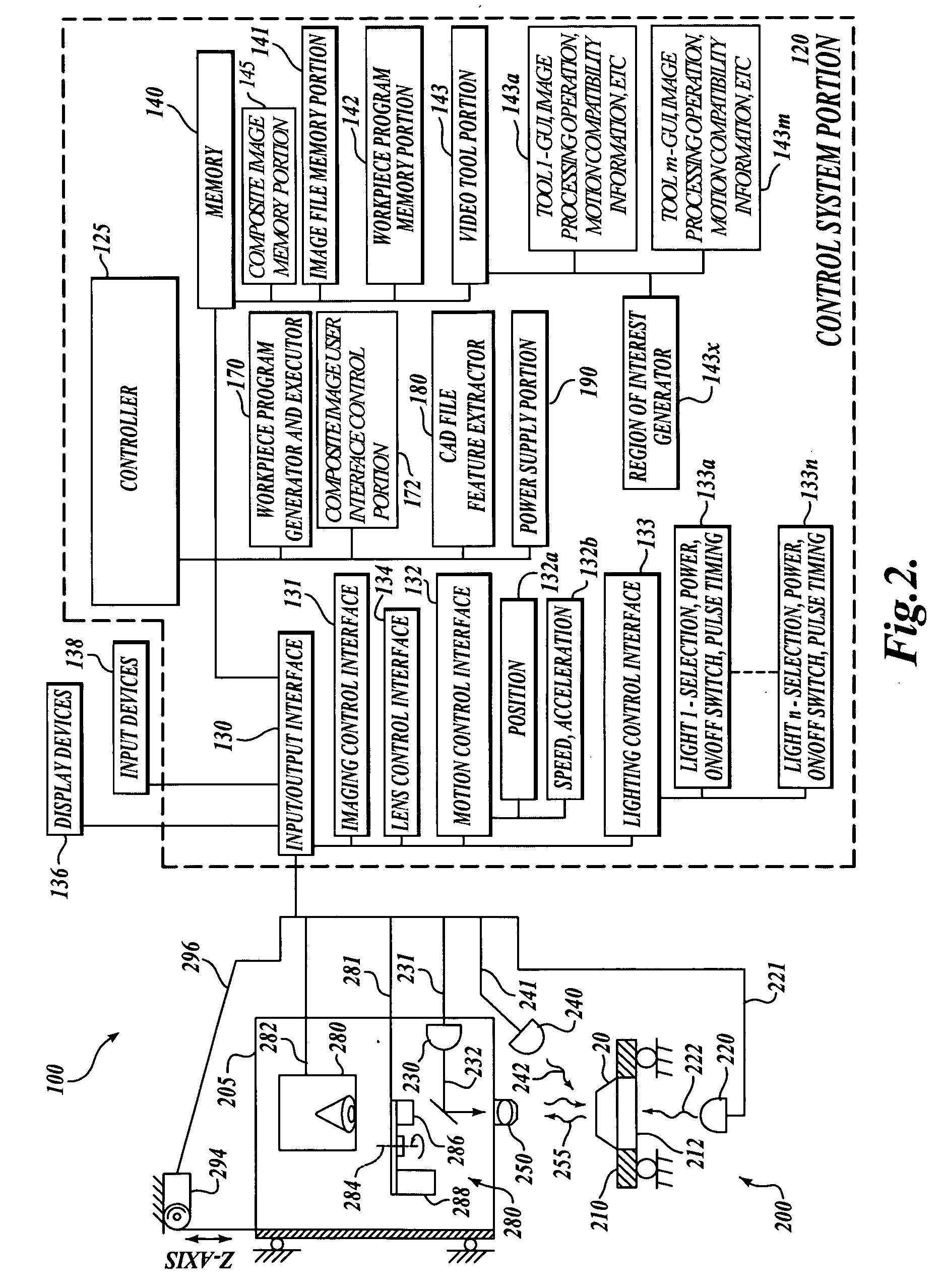
[0024] The vision measuring machine 12 includes a moveable workpiece stage 32 and an optical imaging system 34 which may include...


PUM


Abstract

Improved user interface methods facilitate navigation and programming operations for a magnified machine vision inspection system. Large composite images are determined and stored. The composite images include workpiece features that are distributed beyond the limits of a single magnified field of view of the machine vision system. Despite their size, the composite images may be recalled and displayed in a user-friendly manner that approximates a smooth, real-time, zoom effect. The user interface may include controls that allow a user to easily define a set of workpiece features to be inspected using a composite image, and to easily position the machine vision system to view those workpiece features for the purpose of programming inspection operations for them.

Description

FIELD OF THE INVENTION [0001] The invention relates generally to machine vision inspection systems, and more particularly to methods for providing an improved user interface usable to facilitate navigation and inspection operations for such systems. BACKGROUND OF THE INVENTION [0002] Precision machine vision inspection systems (or “vision systems” for short) can be utilized to obtain precise dimensional measurements of inspected objects and to inspect various other object characteristics. Such systems may include a computer, a camera and optical system, and a precision stage that is movable in multiple directions so as to allow the camera to scan the features of a workpiece that is being inspected. One exemplary prior art system that is commercially available is the QUICK VISION® series of PC-based vision systems and QVPAK® software available from Mitutoyo America Corporation (MAC), located in Aurora, Ill. The features and operation of the QUICK VISION® series of vision systems and ...

Claims


Application Information

Patent Timeline
Patent Type & Authority Applications(United States)
IPC IPC(8): G06K9/00
CPCG06T3/40G06T2200/24
Inventor BRYLL, ROBERT KAMILVENKATACHALAM, VIDYA
Owner MITUTOYO CORP
Why Eureka
Try Eureka