Spherical drill bushing for installing a dental implant

a technology for dental implants and spherical drills, applied in dental tools, dental surgery, medical science, etc., can solve the problems that the drill bushing, unfortunately, can be difficult to attach to the sten

Inactive Publication Date: 2007-04-05
HARTER ROBERT J
View PDF5 Cites 78 Cited by
  • Summary
  • Abstract
  • Description
  • Claims
  • Application Information

AI Technical Summary

Benefits of technology

[0009] Another object of some embodiments is to eliminate the need for a transitional piece between the bushing and the stent.
[0011] Another object of some embodiments is to provide the ball-and-socket joint with an interference fit that prevents the drill bushing from pivoting too freely.

Problems solved by technology

A drill bushing, unfortunately, can be difficult to attach to a stent, particularly if the drill bushing is to be pivotal relative to the stent as is the case in the U.S. Pat. No. 5,718,579 patent.

Method used


Image

  • Spherical drill bushing for installing a dental implant
  • Spherical drill bushing for installing a dental implant
  • Spherical drill bushing for installing a dental implant

Examples


Embodiment Construction

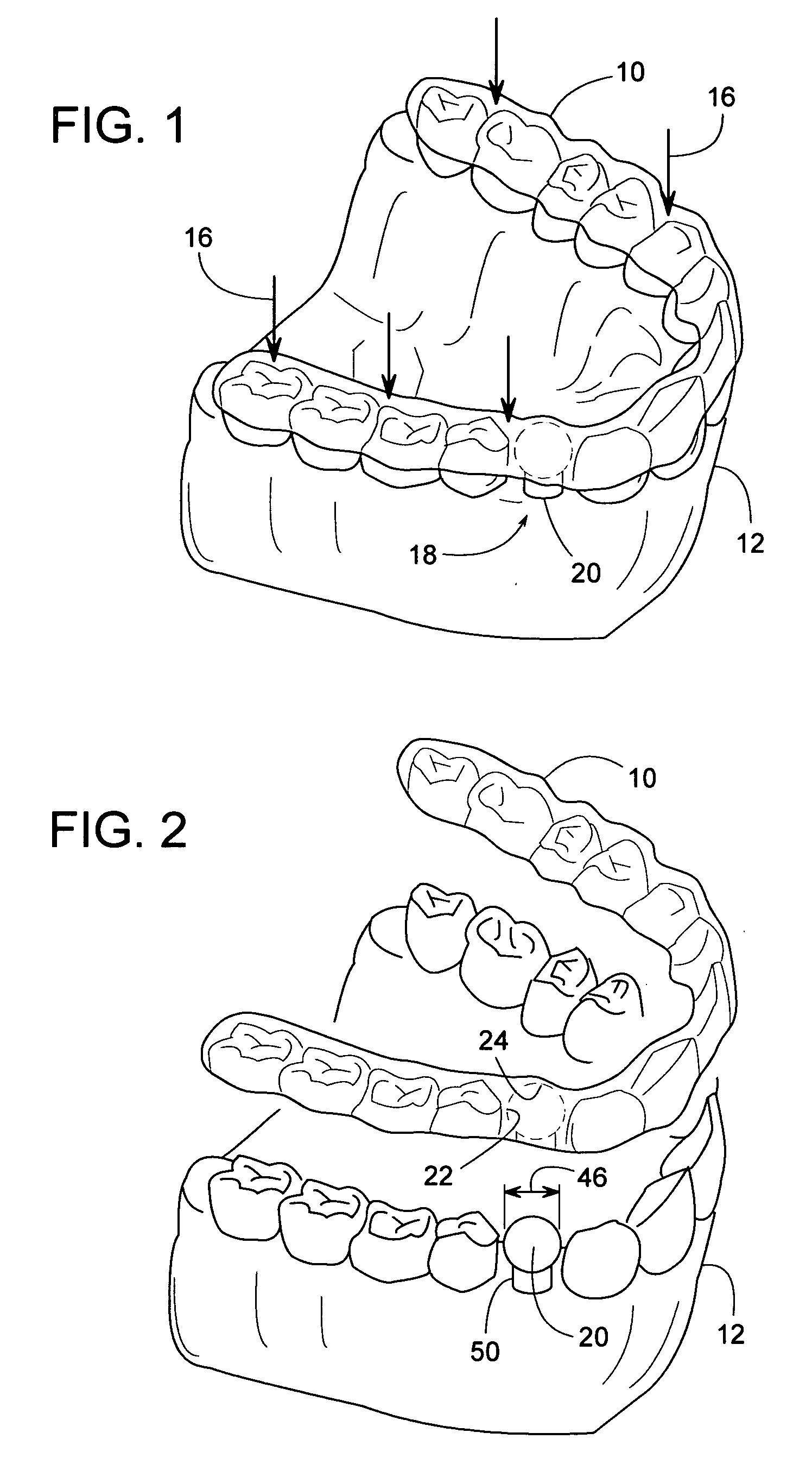
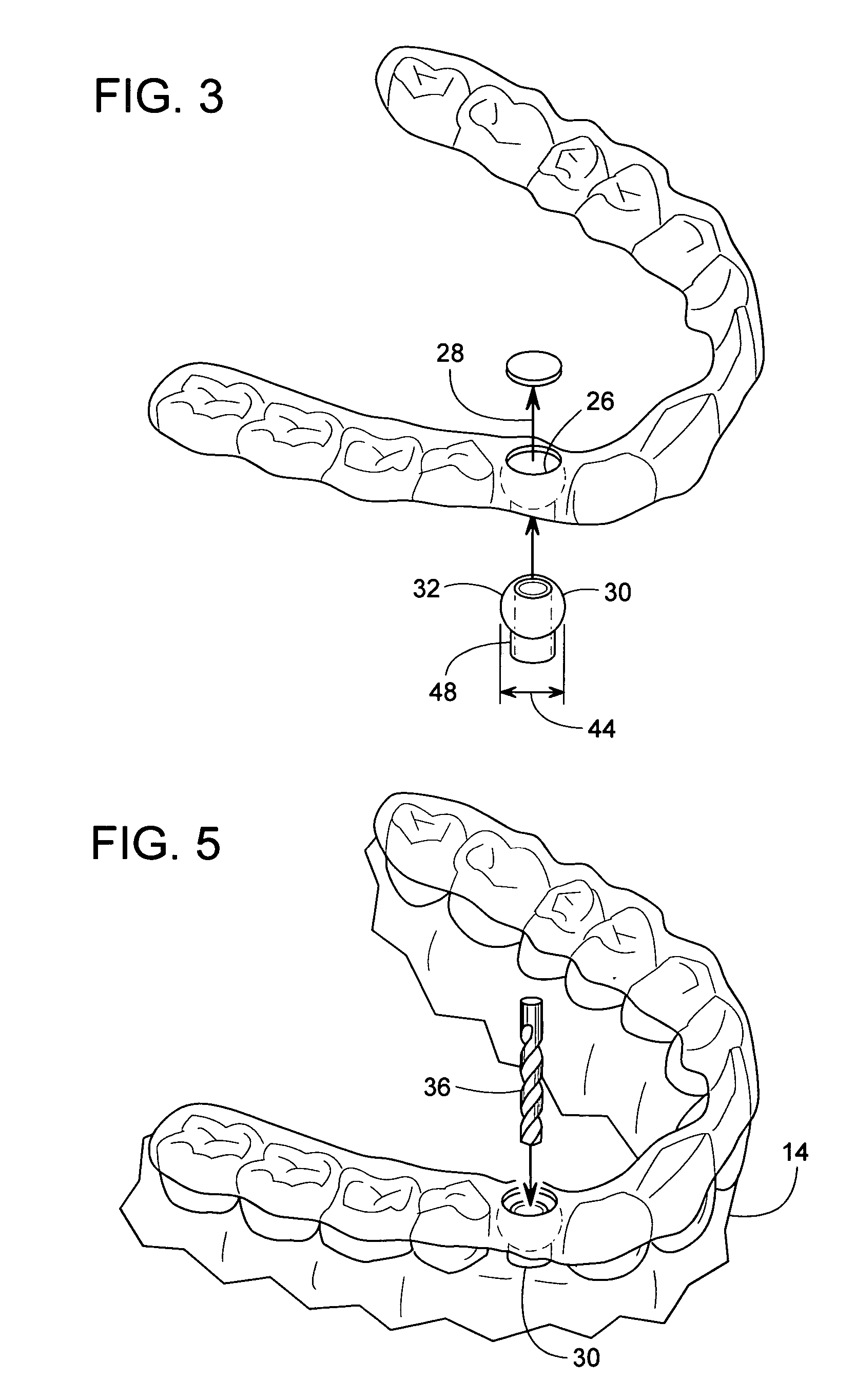
[0028]FIG. 1 shows a surgical dental stent 10 being formed over a model 12 of a patient's actual upper or lower jaw 14 (FIG. 5). Model 12 can be cast or otherwise made in a conventional manner well known to those skilled in the art. The term, “jaw” refers to that part of a patient's body that comprises one or more of the following: teeth, gums, and / or jawbone (upper or lower). Stent 10 is a conventional surgical dental stent that can be produced in various ways that are well known to those skilled in the art. Arrows 16 schematically represent a vacuum forming process as well as other common methods of making a stent. Stent 10 can be hollow or solid in an area 18 of the missing tooth.

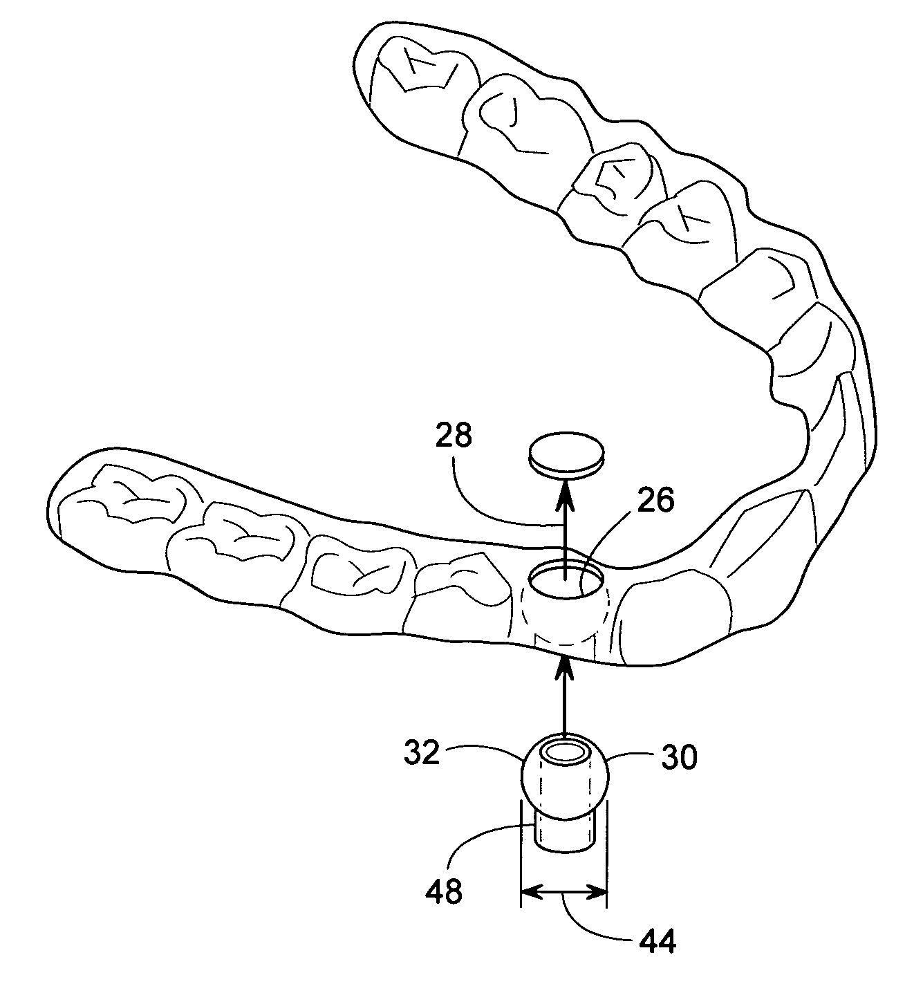
[0029] In some cases, a plug 20 is placed on model 12 in the area of the missing tooth to create a concavity 22 in stent 10 as stent 10 is being formed. Concavity 22 preferably has a substantially spherical concave surface 24; however other surface shapes are possible.

[0030]FIG. 2 shows stent 10 with c...


PUM


Abstract

A dental tool for guiding a drill bit during a dental implant procedure includes a drill bushing that is pivotally attached to a stent, wherein the drill bushing has a generally spherical surface that directly engages the stent.

Description

BACKGROUND OF THE INVENTION [0001] 1. Field of the Invention [0002] The subject invention generally pertains to dental implants and more specifically to a tool for installing them. [0003] 2. Description of Related Art [0004] Various dental implant methods and devices have been developed for replacing one or more missing teeth in a person's jaw with prosthetic teeth. For many prosthetic teeth, a final product comprises three basic components: an implant, an abutment, and a crown. The crown is the exposed portion of the prosthesis that resembles one or more teeth. The implant is an anchor that becomes attached to the jawbone, and the abutment couples the crown to the implant. [0005] To install the implant, a hole is usually drilled into the patient's jawbone, and the implant is inserted into the hole. [0006] A drill bushing attached to a stent can be used to help guide the drill bit, as disclosed in PCT Publication WO 99 / 26540 and U.S. Pat. Nos. 5,015,183; 5,133,660; 5,718,579. A dril...

Claims


Application Information

Patent Timeline
Patent Type & Authority Applications(United States)
IPC IPC(8): A61C3/00A61C1/08A61C8/00
CPCA61C1/084A61C8/0089
Inventor HARTER, ROBERT J.
Owner HARTER ROBERT J
Why Eureka
Try Eureka