Two-stroke engine

a two-stroke engine and crankcase technology, applied in combustion engines, machines/engines, mechanical equipment, etc., can solve the problems of low emission of nosub>x /sub>x, inherently low emission of unburned hydrocarbons (uhc) and carbon monoxide (co), and severe drawbacks in engine cooling, lubrication and engine behaviour

Active Publication Date: 2007-04-12
HUSQVARNA AB
View PDF6 Cites 3 Cited by
  • Summary
  • Abstract
  • Description
  • Claims
  • Application Information

AI Technical Summary

Benefits of technology

[0028] The present invention solves these and other problems by providing a crankcase scavenged two-stroke engine in which the transfer duct volume is less than 20% of a volume swept by the piston during an entire revolution of the crankshaft. Further, the engine is provided with recesses formed in an outer periphery of the piston, said recesses co-operating with the connecting ports in the cylinder wall for controlling the filling of the transfer duc...

Problems solved by technology

The major problem with small, crankcase scavenged, carburetted two-stroke engines is the emission level of unburned hydrocarbons (uHC) and carbon monoxide (CO).
Legislation also requires low amounts of nitric oxides (NOx), but due to the general function of two-stroke engines, the emission of NOx is inherently low.
Leaning out the fuel/air mixture has however some severe drawbacks regarding engine cooling, lubrication and engine behaviour.
The reasons for this are; The temperature in the combustion chamber does not reach high levels, due to fuel rich combustion and excessive dilution of the combustible fuel/air mixture with exhaust gases.
Wall quenching means that the combustion flame is not able to travel all the way to a combustion chamber wall, leaving an unburned zone close to the combustion chamber walls.
Incomplete combustion mainly occurs when the fuel air mixture is too diluted with an excessive air or exhaust gas amount to burn.
Hence, an air-head scavenging system starts by letting pure air flow through the transfer channels, which increases the probability that pure air is short-circui...

Method used


Image

  • Two-stroke engine
  • Two-stroke engine

Examples


Embodiment Construction

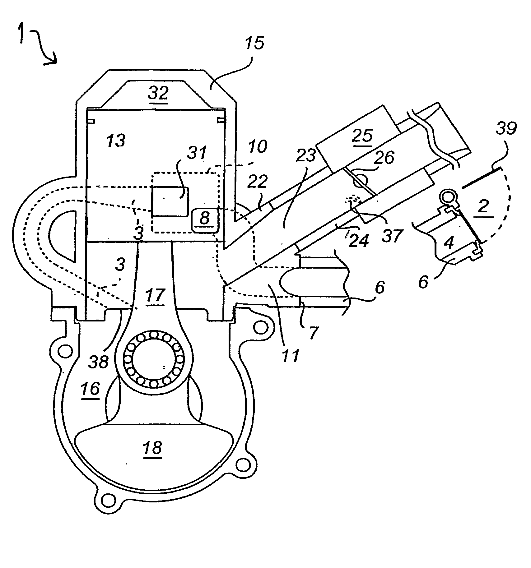
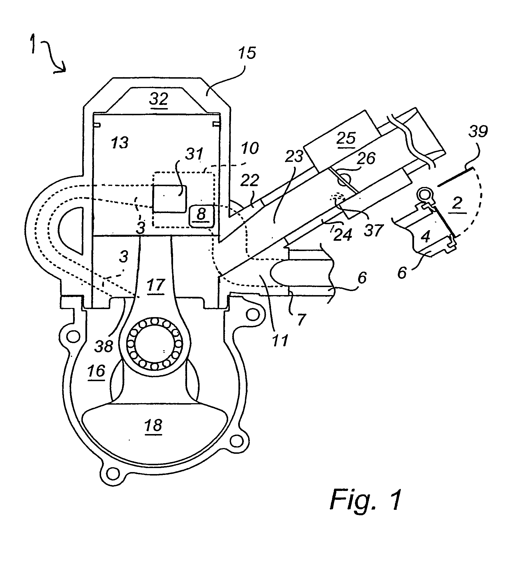
[0031] In this description, like reference numerals of which one is denoted with implies that there are identical components on opposite sides of the engine. Due to clarity reasons, only one of such components is shown in the drawing

[0032] In FIG. 1, a carburetted two-stroke engine 1 utilising an “air-head” scavenging system is shown. The engine comprises a cylinder 15 and a piston 13 being connected to a crankshaft 18 by means of a connecting rod 17, which piston in co-operation with the cylinder defines a combustion chamber 32. The piston is also equipped with flow paths 10, 10′, in the form of recesses. The function of these recesses will be described in the following. Further, the engine comprises an inlet 22 connected to a carburettor, or fuel dosage means, 37 by an inlet duct 23. The piston, the lower end of the cylinder and a crankcase define a generally sealed crankcase volume 16, into which the inlet 22 opens. The crankcase is connected to the cylinder by means of transfer...


PUM


Abstract

A crankcase scavenged two-stroke engine (1) comprises a cylinder (15) including scavenging ports (31, 31′) and at least one exhaust port, a piston (13), a connecting rod (17), a crankshaft (18) and a generally sealed crankcase (16). The crankcase inducts a fuel/air mixture and is connected to the scavenging ports (31, 31′) by means of transfer ducts (3, 3′) which, as the piston (13) is travelling from a lower position towards a higher position, are inducting pure air let in from connecting ports (8, 8′) near the scavenging ports (31, 31′) in the cylinder (15). The transfer duct (3, 3′) volume is less than 20% of a volume swept by the piston (13) during an entire revolution of the crankshaft (18). Recesses (10, 10′) are formed in an outer periphery of the piston (13), said recesses (10, 10′) co-operating with the connecting ports (8, 8′) in the cylinder wall for controlling the filling of the transfer ducts (3, 3′) with air. An inlet tube (22) in the cylinder wall supplies the air/fuel mixture, said inlet tube (22) being connected to the crankcase (16) and covered by the piston (13) as the piston (13) is in the lower position, and open to the crankcase (16) as the piston (13) is in the higher position.

Description

FIELD OF THE INVENTION [0001] The present invention relates to a crankcase scavenged two-stroke engine comprising a cylinder including scavenging ports and at least one exhaust port, a piston, a connecting rod, a crankshaft and a generally sealed crankcase. The crankcase inducts a fuel / air mixture and is connected to the scavenging ports by means of transfer ducts. As the piston is travelling from a lower position towards a higher position, the transfer ducts are inducting pure air let in from connecting ports near the scavenging ports in the cylinder. [0002] The present invention further relates to a scavenging method for a crankcase scavenged two-stroke engine of the above-mentioned type. BACKGROUND OF THE INVENTION [0003] small, carburetted two-stroke engines are mainly used for hand-held tools, like e.g. chain saws, weed cutters, trimmers, lawn mowers, etc. The main reasons for using two-stroke engines for such tools / machines are that they are cost effective and that they have a...

Claims


Application Information

Patent Timeline
IPC IPC(8): F02B25/22F02B1/12
CPCF02B1/12F02B25/22
Inventor MARTINSSON, PARBERGMAN, MIKAELGUSTAFSSON, REINE
Owner HUSQVARNA AB
Why Eureka
Try Eureka