Engine balancer apparatus

a technology of balancer and engine, which is applied in the direction of spring/damper, machine/engine, shaft, etc., can solve the problems of vibration generation noise, vibrations, and contribute to wear, and achieve the effect of suppressing vibrations in the engin

Inactive Publication Date: 2007-04-12
GASOLINEIAM NASIONAL BERHAD
View PDF8 Cites 27 Cited by
  • Summary
  • Abstract
  • Description
  • Claims
  • Application Information

AI Technical Summary

Benefits of technology

[0007] The present invention relates to a balancer apparatus for suppressing vibrations in an engine and, more particularly, to a compact balancer apparatus which suppresses or cancels inertial force and / or inertial couple forces induced by pistons, connecting rods, shafts and the like when the engine is running. The balancer apparatus can be used on a large variety of internal combustion engines having a various number of pistons, and is particularly suited four cylinder engines and more particularly suited for inline-four cylinder engines.
[0008] The balancer apparatus generally includes a first balancer having a first balance weight and a second balancer having a second balance weight, wherein the first and second balance weights are not identical. The first balancer includes a driven gear and a secondary driving gear, while the second balancer includes a secondary driven gear engaging the secondary driving gear. The second balance weight includes a primary balance portion and a secondary balance portion set back from the primary balance portion. More specifically, the primary balance portion and the secondary balance portion define a setback cutout that allows the driven gear to fit within the setback cutout when the first balancer is operationally coupled the second balancer. This interrelationship of the balancers allows for a more compact balancer assembly. Each of the balancers has a center of gravity, and when arranged in the housing, the center of gravities are aligned along the axes. Of course, because the balancer assembly creates vibrations the center of gravities alignment laterally from the axes may be different.

Problems solved by technology

When individual movable portions of an engine become off balance during operation, vibrations occur.
Such vibrations generate noise, contribute to wear, and may be felt by the operator or occupants of a vehicle containing the engine.
One problem with existing balancer assemblies is that the mass required to produce sufficient vibrations makes it difficult to assemble a compact balancer assembly for use in today's compact engines and engine compartments.
Most balancer assemblies include balancers with radiuses or lengths that are too large to be easily configured for today's compact engines and engine compartments or are not as effective as desired in reducing engine vibrations.
Most balancers are long, bulky, and heavy.
Another problem with many existing balancer shafts is that the long, bulky, and heavy balancers require bulky, heavy and rigid housings.
This may require an increased oil sump size, which may cause problems in today's space restricted engine compartments.
Another problem is that due to a large housing, especially when the oil sump has been designed to fit within a compact engine compartment, the maximum oil volume that can be filled into the oil sump is generally less than desired due to the large portion of the oil sump volume required by the housing.
The housing for the balancers may also restrict the movement of airflow in and above the oil sump and thereby potentially causes significant power reduction in the engine.

Method used


Image

  • Engine balancer apparatus
  • Engine balancer apparatus
  • Engine balancer apparatus

Examples


Embodiment Construction

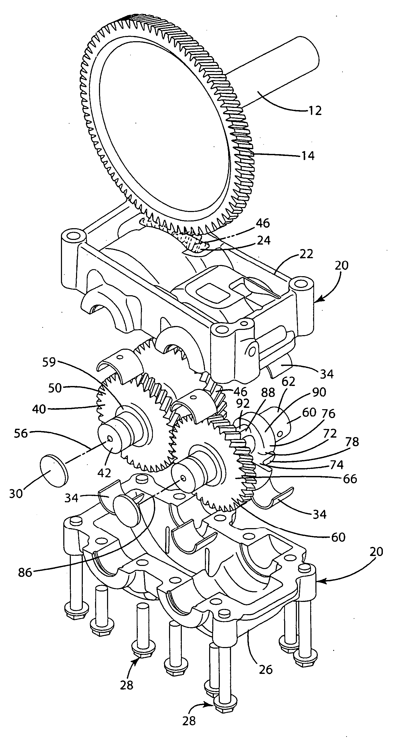
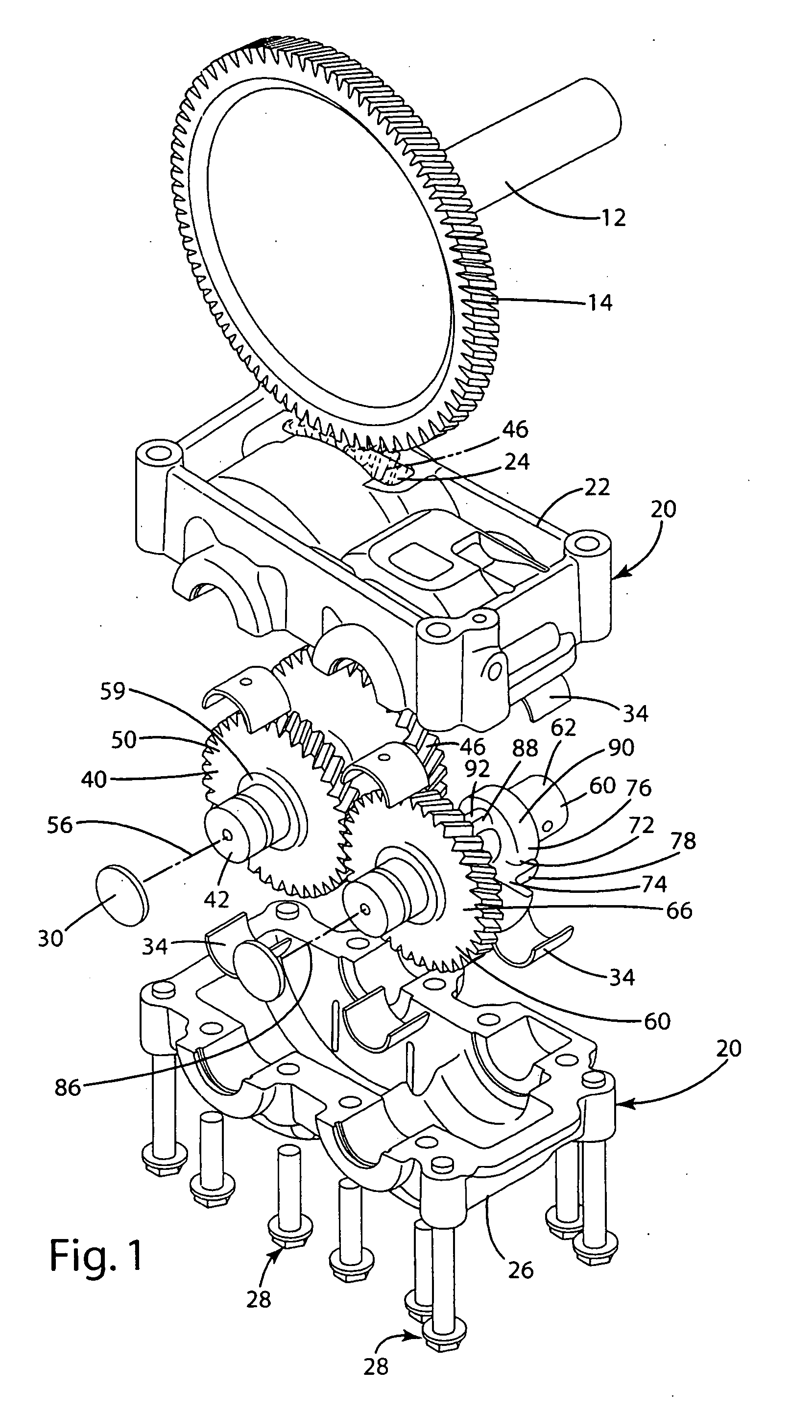
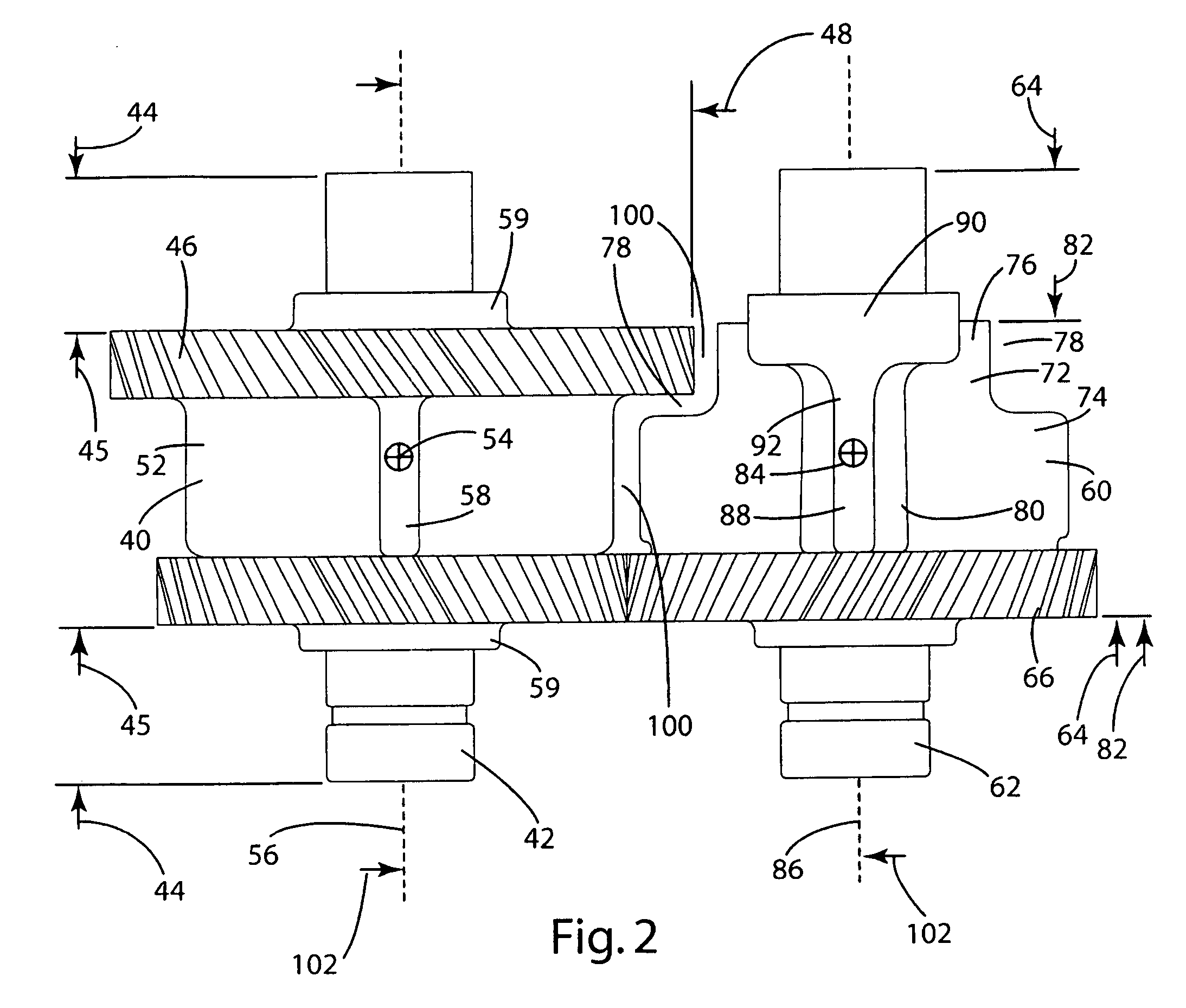
[0018] A balancer assembly 10, mounted on an internal combustion engine (not shown) and operably connected to the crankshaft 12 of the engine, through the crankshaft gear 14, is illustrated in FIG. 1. The balancer assembly 10 generally includes a first balancer 40 operably coupled to a second balancer 60. The first and second balancers 40, 60 are asymmetrical and secured within a cover assembly 20. The asymmetrical shape of the first and second balancers 40, 60 allows for a compact yet efficient balancer assembly 10 for suppressing or reducing engine vibrations.

[0019] The cover assembly 20, as illustrated in FIG. 1, includes an upper cover 22, a lower cover 26, and a fastener assembly 28. The fastener assembly 28 fastens both the upper cover 22 to the lower cover 26 as well as the cover assembly 20 to the engine. In the illustrated embodiment, the upper cover 22 includes a gear recess 24 to allow the crankshaft gear 14 to be coupled to the first balancer 40. The cover assembly 20 m...


PUM


Abstract

A balancer apparatus including a first balancer and a second balancer. The first balancer includes a first balance weight and the second balancer includes a second balance weight and wherein the first and second balance weights are asymmetrical. The first and second balancers include first and second center of gravities that are longitudinally aligned when the first and second balancers are assembled in a housing.

Description

CROSS-REFERENCE TO RELATED APPLICATION [0001] This application is based upon and claims priority to Malaysian Patent Application No. PI 20054776, filed Oct. 11, 2005, which application is hereby expressly incorporated by reference. BACKGROUND OF THE INVENTION [0002] The present invention relates to a balancer apparatus for suppressing vibrations in an engine and, more particularly, to a compact balancer apparatus which suppresses or cancels out inertial force and / or inertial couple forces induced by pistons, connecting rods, shafts and the like when the engine is running. [0003] When individual movable portions of an engine become off balance during operation, vibrations occur. Such vibrations generate noise, contribute to wear, and may be felt by the operator or occupants of a vehicle containing the engine. To reduce these vibrations, a balancer assembly is typically used to cancel or suppress vibrations of the engine. The balancer assembly operates by providing vibrations opposite...

Claims


Application Information

Patent Timeline
Patent Type & Authority Applications(United States)
IPC IPC(8): F02B75/06F16C11/00
CPCF02B75/06Y10T74/2183Y10T74/2184F16F15/265
Inventor OSMAN, AZMI B.
Owner GASOLINEIAM NASIONAL BERHAD
Why Eureka
Try Eureka