Method for operating an internal combustion engine

a technology of internal combustion engine and internal combustion chamber, which is applied in the direction of fluid tightness measurement, electric control, instruments, etc., can solve the problem that the continuous operation of the internal combustion engine is no longer useful, and achieve the effect of simple fashion

Inactive Publication Date: 2007-04-12
ROBERT BOSCH GMBH
View PDF6 Cites 25 Cited by
  • Summary
  • Abstract
  • Description
  • Claims
  • Application Information

AI Technical Summary

Benefits of technology

[0012] A further advantage may be obtained if, for the determination of the pressure decay rate, a high-pressure circuit is separated from a low-pressure circuit of the fuel delivery system, and the pressure decay rate in the high-pressure circuit is determined. The pressure decay rate can thereby be de

Problems solved by technology

This takes into account the fact that at idle or a low load, continued operation of the internal combustion engine is no lo

Method used


Image

  • Method for operating an internal combustion engine
  • Method for operating an internal combustion engine
  • Method for operating an internal combustion engine

Examples


Embodiment Construction

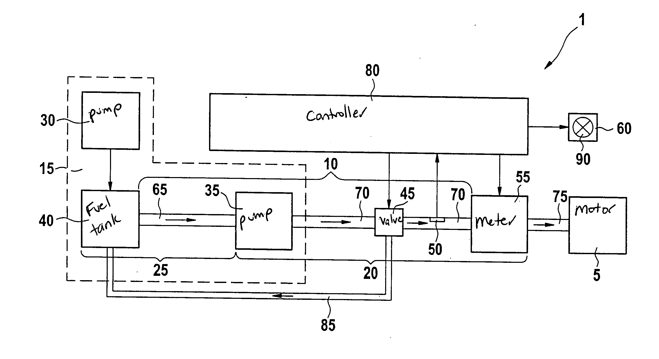
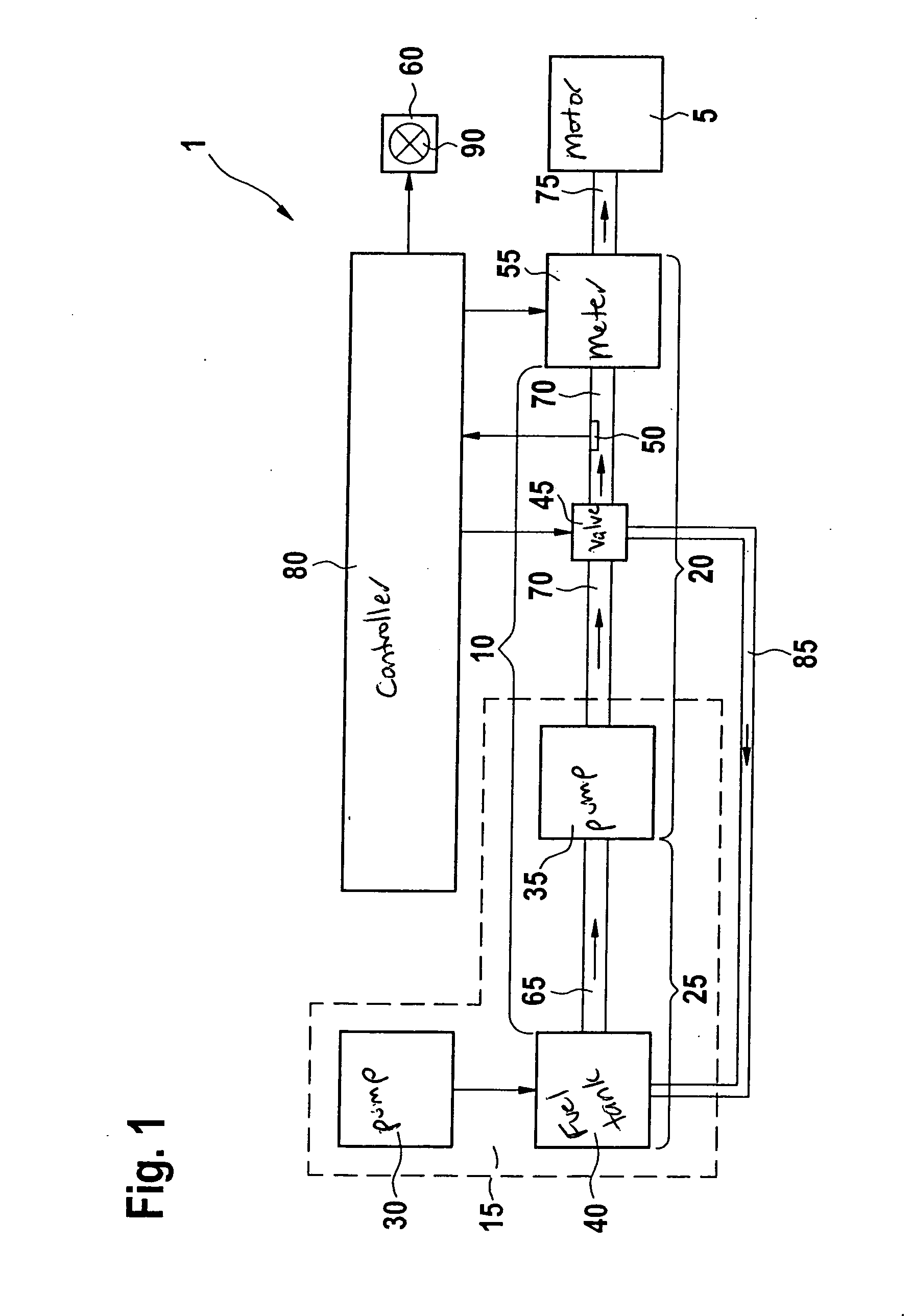
[0017] In FIG. 1, 1 designates an internal combustion engine that, for example, drives a vehicle. Internal combustion engine 1 encompasses a fuel-operated combustion motor 5 that can be embodied, for example, as a spark-ignited engine or diesel engine.

[0018] Internal combustion engine 1 furthermore encompasses a fuel supply system 15 that supplies fuel to combustion motor 5 through a fuel delivery system 10. Fuel supply system 15 encompasses a mechanically or electrically driven conveying pump 30 that pumps fuel out of a fuel tank 40 into fuel delivery system 10 toward combustion motor 5. A (for example, mechanical) pressure regulator having a pressure valve can be connected in parallel with conveying pump 30. A fuel filter can also be disposed at the outlet of fuel tank 40. This is not depicted in FIG. 1 for reasons of clarity. From fuel tank 40, fuel is pumped first into a low-pressure line 65, in which context conveying pump 30 generates, for example, an inlet pressure of approx...


PUM


Abstract

A method for operating an internal combustion engine having a fuel-driven combustion motor, making possible a differentiation of faults in the fuel delivery system. Fuel is delivered under pressure to the combustion motor via a fuel delivery system. A pressure decay rate in the fuel delivery system is determined, and a fault is inferred as a function of a comparison of the pressure decay rate with a predefined threshold value.

Description

FIELD OF THE INVENTION [0001] The present invention relates to a method for operating an internal combustion engine. BACKGROUND INFORMATION [0002] Several methods for operating an internal combustion engine having a fuel-driven combustion motor are conventional. In this context, fuel is conveyed under pressure to the combustion motor via a fuel delivery system, the pressure in the fuel delivery system being regulated to a setpoint. SUMMARY [0003] A method according to an example embodiment of the present invention may have an advantage that a pressure decay rate in the fuel delivery system is determined; and that a fault is inferred as a function of a comparison of the pressure decay rate with a predefined threshold. In this fashion, all the sealing failures in a high-pressure circuit of the fuel delivery system can be recognized, and can be differentiated from other faults in the fuel supply system. [0004] It may be particularly advantageous if for the case in which an actual value...

Claims


Application Information

Patent Timeline
IPC IPC(8): F02D41/22F02D41/38
CPCF02D41/22F02D41/3836F02D41/3863F02D2041/223F02D2041/225F02D2041/227F02D2041/228
Inventor DINGLER, THOMASLAUTER, STEFANDEGEL, ACHIM
Owner ROBERT BOSCH GMBH
Why Eureka
Try Eureka