MEMS sensor package leak test

a sensor and leakage test technology, applied in the field of microelectromechanical systems (mems) sensors, can solve the problems of gas leakage into or out of the sensor cavity, leakage of internal package pressure, and sensor seals often not having perfect seals

Inactive Publication Date: 2007-04-19
HONEYWELL INT INC
View PDF10 Cites 23 Cited by
  • Summary
  • Abstract
  • Description
  • Claims
  • Application Information

AI Technical Summary

Benefits of technology

[0010] In some cases, the chamber may be pressurized before the sensor parameter is measured at the first time. Also, the chamber may be depressurized before the sensor parameter is measured at the second time, o

Problems solved by technology

The packages for many MEMS sensors often do not have perfect seals, which results in gas leakage into or out of the sensor cavity.
Over time, these leaks can change the internal package pressure, and thus may affect the Q value of the sensor.
In some cases, a relatively small leak can cause a relatively large change in pressure in the sensor cavity, particularly over long p

Method used


Image

  • MEMS sensor package leak test
  • MEMS sensor package leak test
  • MEMS sensor package leak test

Examples


Embodiment Construction

[0019] The following description should be read with reference to the drawings wherein like reference numerals indicate like elements throughout the several views. The detailed description and drawings show several embodiments, which are meant to be illustrative of the claimed invention.

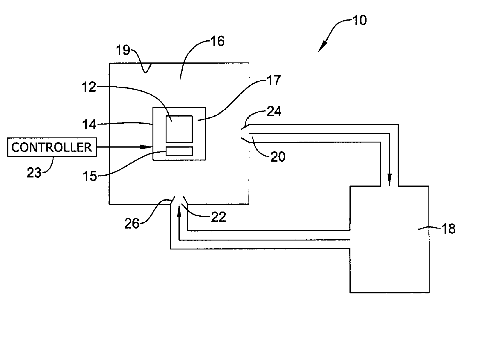
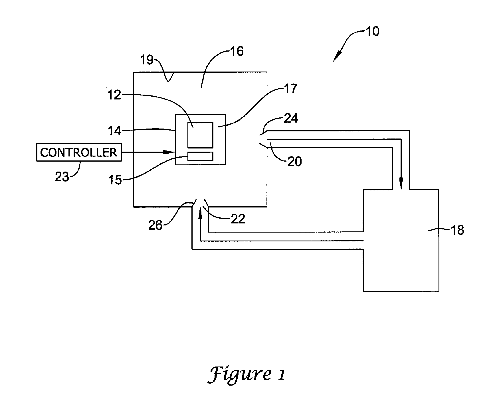
[0020] In some applications, it is desirable to provide a MEMS sensor with an expected useful life in the range of 10 to 20 years, or greater. MEMS sensors for the automotive industry may be one such application. To have a relatively long life, a MEMS sensor package must typically maintain a pressure limit in a sensor cavity over the expected useful lifetime of the MEMS sensor. For example, and in one application, the pressure in the sensor cavity must be less than 47 mTorr over the expected lifetime of the MEMs sensor. Other applications may have higher or lower pressure limits for the MEMS sensor package, as desired. In one case, the MEMS sensor package may have a sensor cavity with a volume of 0....


PUM


Abstract

Methods and apparatus are provided for detecting leaks in a MEMS sensor package, and in particular, a MEMS sensor package that includes an oscillating structure or element that has a Quality (Q) value. The method and apparatus may include measuring the Q value of the MEMS sensor at a first time, applying a pressure to the outside of the MEMS sensor package, and measuring the Q value of the MEMS sensor at a second time after pressure has been applied for a period of time. A change in the measured Q values between the first time and the second time may be determined, which may then be correlated to a leak rate for the particular MEMS sensor package. In some cases, a leak rate of 2×10⁻¹³ He atm.cc/s or less may be detected.

Description

FIELD [0001] The present invention relates generally to micro-electro-mechanical systems (MEMS) sensors, and more particularly, to methods and systems for detecting leaks in packages that house a MEMS sensor that includes a mechanical oscillator element. BACKGROUND [0002] Many MEMS sensors include a mechanical oscillator element. For example, MEMS gyroscope and / or accelerometer type sensors often include one or more proof masses, tuning forks or other oscillating structures that are electrostatically driven at a resonance frequency. Movements of the sensor housing, such as rotational movement, lateral movement, acceleration, or other movement can then be detected by sensing certain behavior in the oscillating structure. For example, the oscillating structure may move in a direction that is perpendicular to the oscillating direction due to externally applied forces, such as coriolis forces, acceleration forces, or other forces, depending on the application. [0003] The operational per...

Claims


Application Information

Patent Timeline
IPC IPC(8): G01M3/04
CPCG01M3/3281
Inventor JARRETT, MARK J.
Owner HONEYWELL INT INC
Why Eureka
Try Eureka