

Press-bonding apparatus and press-bonding method
a press-bonding and press-bonding technology, which is applied in the direction of electrical equipment, printed circuits, manufacturing tools, etc., can solve the problems of defective connection, difficult maintenance, and the bonding member cannot be adequately heated, so as to prevent damage to the substrate
- Summary
- Abstract
- Description
- Claims
- Application Information
AI Technical Summary
Benefits of technology
Problems solved by technology
Method used
Image

Examples
Embodiment Construction
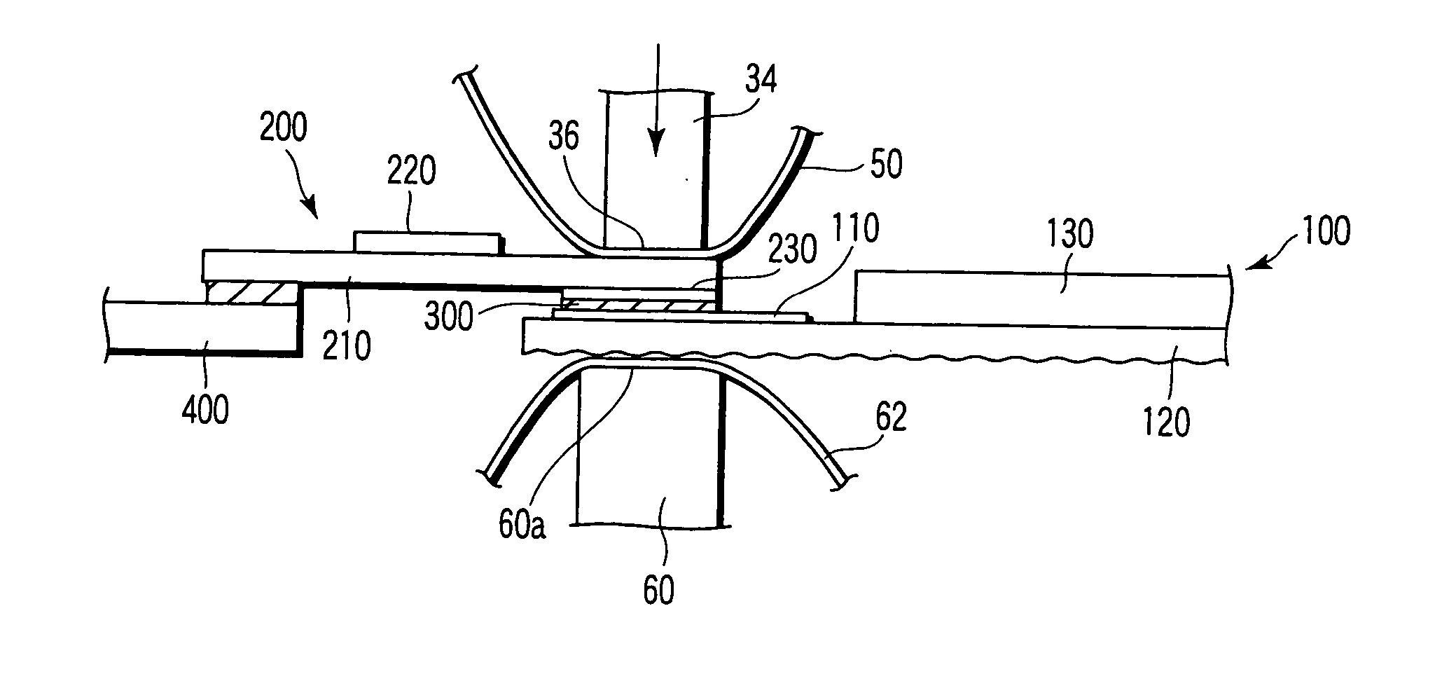
[0024] Referring now to the accompanying drawings, a description will be given of a manufacturing apparatus and a manufacturing method for a display device according to an embodiment of the present invention, in particular, a press-bonding apparatus and a press-bonding method for connecting a display panel and a wiring board, which constitute the display device.
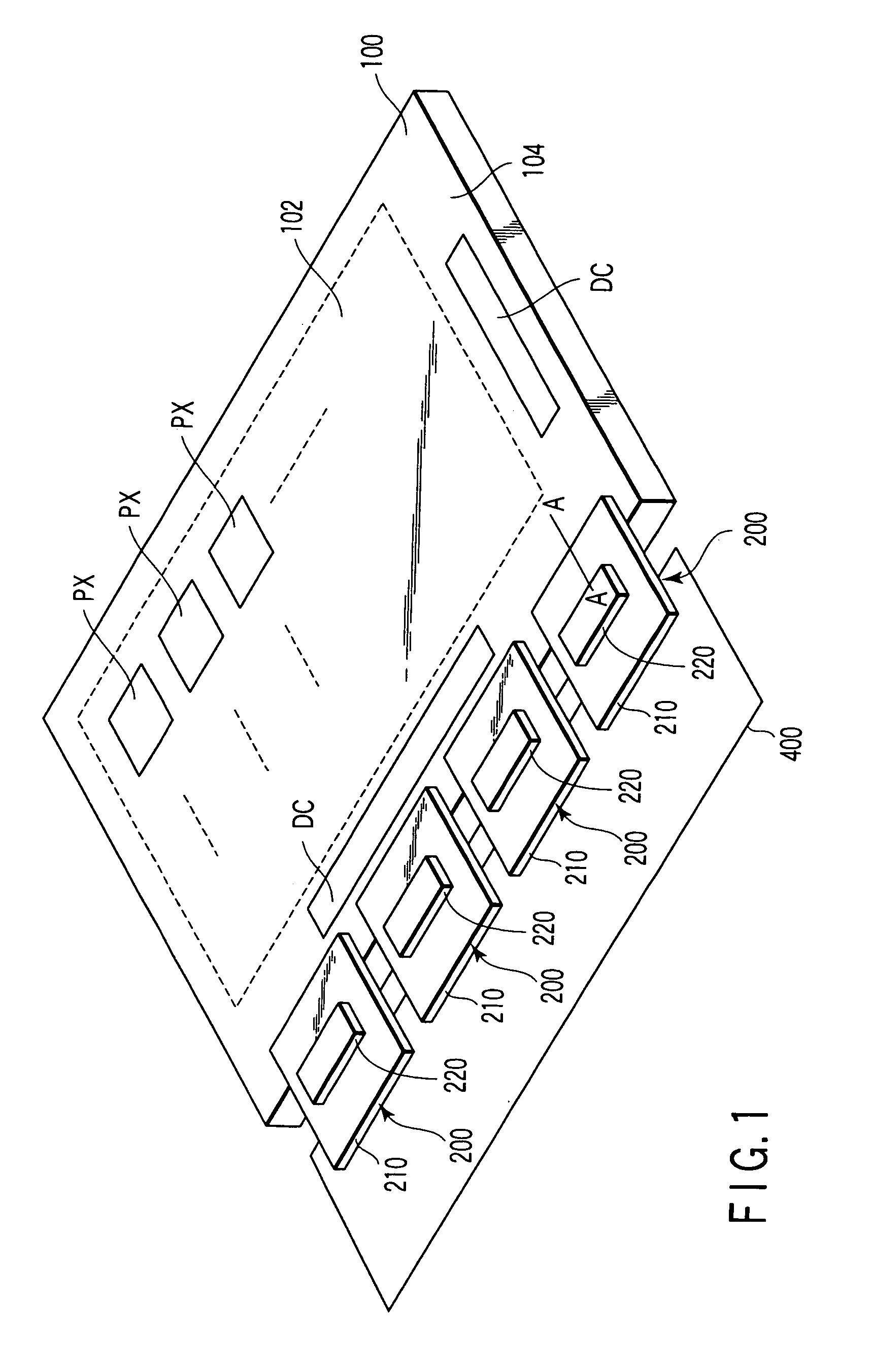
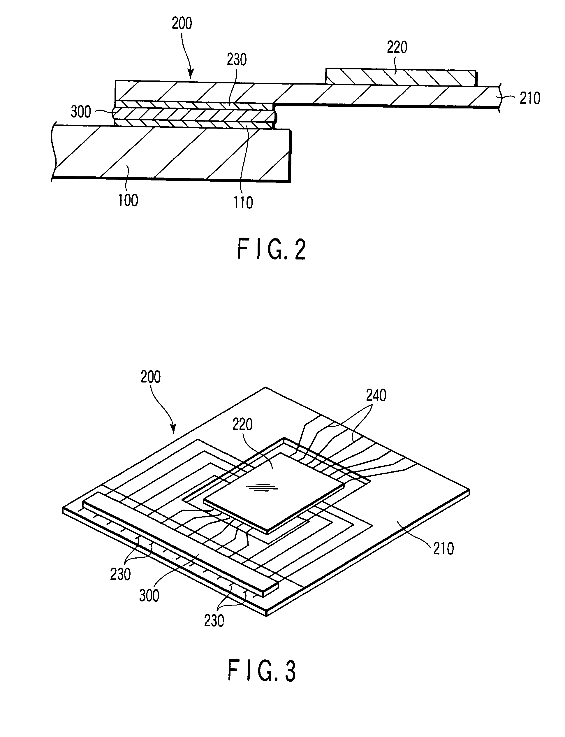
[0025] To begin with, the structure of a display device, which is the object of manufacture, is described. As shown in FIG. 1 and FIG. 2, the display device includes a flat-plate-shaped display panel 100. The display panel 100 is formed by using a very thin insulating substrate (glass substrate with a thickness of, e.g. 0.3 mm), and the display panel 100 includes a display area 102 which displays an image. The display area 102 is composed of a plurality of display pixels PX which are arrayed in a matrix. The display panel includes, in a peripheral area 104 surrounding the display area 102, driving circuits DC for generating ...
PUM
| Property | Measurement | Unit |
|---|---|---|
| Thickness | aaaaa | aaaaa |
| Thickness | aaaaa | aaaaa |
| Thickness | aaaaa | aaaaa |
Abstract
Description
Claims
Application Information