Assist Rod and Basket Assembly

a technology of baskets and rods, applied in the direction of transportation and packaging, railway signalling, roads, etc., can solve the problems of requiring unusually long ties to maintain the clearance necessary, and affecting the operation of the switch. , to achieve the effect of avoiding the need to worry

Inactive Publication Date: 2007-04-19
CLICK GARY +1
View PDF1 Cites 4 Cited by
  • Summary
  • Abstract
  • Description
  • Claims
  • Application Information

AI Technical Summary

Benefits of technology

[0014] The head of the basket comprises a bore for receiving a pin for rotation in the bore. A pair of link arms extend from the ends of the pin. The link arms engage the assist rod to cause it to rotate when the basket undergoes lateral movement transverse to the assist rod. The assist rod is separately mounted for rotation in a sleeve on a support clip. The basket comprises an internal structure similar to prior art structures. A threaded connector rod slidably extends through the basket. Movement of the basket in relation to the connector rod is limited by nuts threaded onto the rod at each end of the basket. Adjustment of the nuts serves to adjust the amount of lost motion to be taken up by the basket before actuating the connector rod by abutment of the basket with the nuts.
[0016] The provision of the baskets in hollow ties avoids the need to worry about the baskets interfering with tamping.
[0017] The invention allows for a more compact switch assembly in which the baskets and the assist rod may be located on the same side of the rails as the switch machine. This in turn allows for the use of shorter ties.

Problems solved by technology

Juxtaposing the switch machine and the assist rod would require unusually long ties to maintain the necessary clearance.
One disadvantage of prior art assist rod assemblies is that the basket is located between the rails to allow for tamping on the outside of the rails.
However, the location of the baskets between the rails results in limited accessibility due to hot air ducts used for snow removal that are frequently mounted between the rails over the top of the basket.
In the case of crowded rail yards, the loss of space resulting from adjacent switches becomes critical.

Method used


Image

  • Assist Rod and Basket Assembly
  • Assist Rod and Basket Assembly
  • Assist Rod and Basket Assembly

Examples


Embodiment Construction

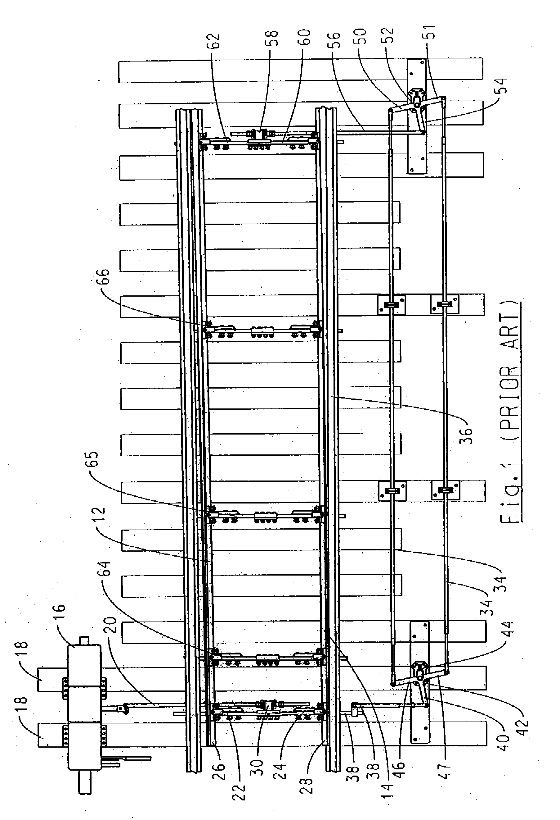
[0031]FIG. 1 illustrates a fairly typical prior art switch layout in which the assist rod and basket assembly is shown. The switch is used to throw the switch point (rails 12, 14).

[0032] A switch machine 16 is mounted on the outside of the rails on a switch stand plate attached to the ends of elongated ties 18. Switch machine 16 actuates a throw rod 20 that is connected to a pair of switch rods 22, 24 connected end to end and extending between the points 26, 28 of the switch point rails.

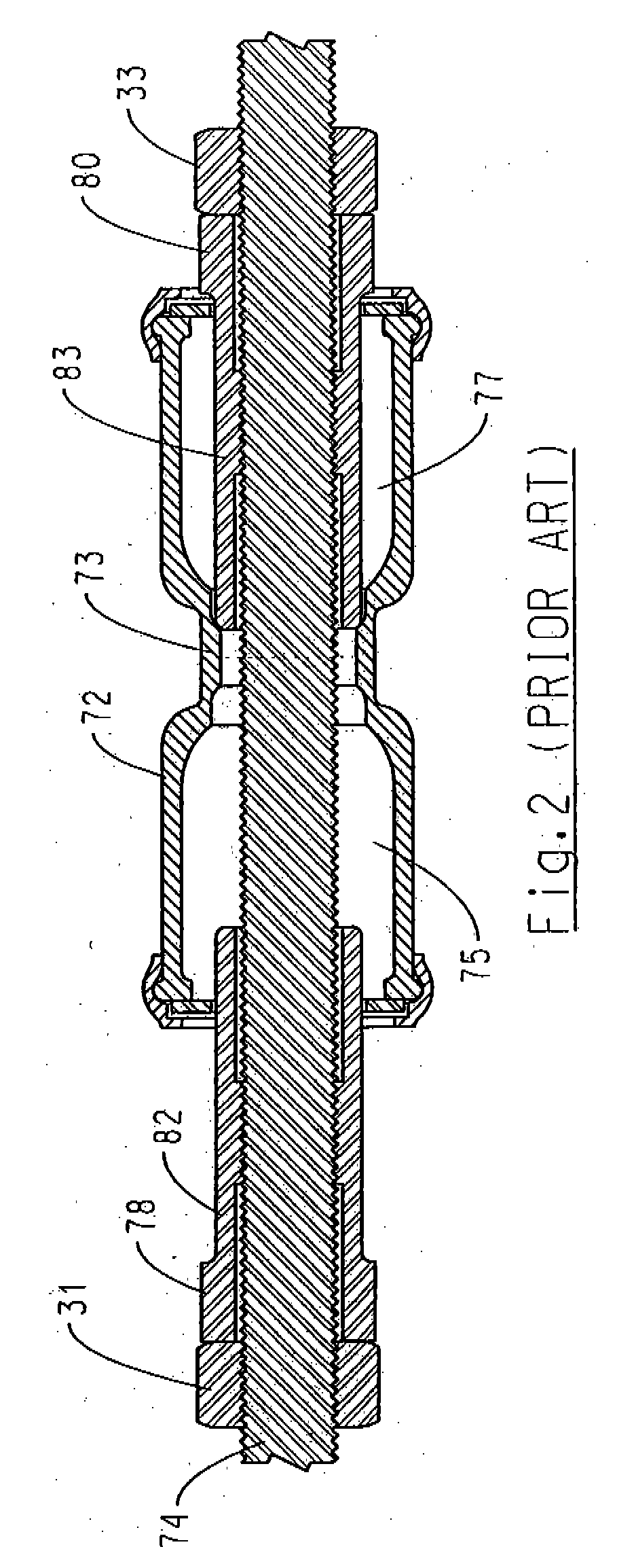
[0033] A front basket 30 is disposed between the throw rod 20 and the switch rods 22, 24. As is known, the basket 30 is adapted to slide a predetermined amount along the throw rod 20 before the basket will engage so as to actuate movement of the switch rods. As will be appreciated by reference to FIG. 2, the predetermined amount may be adjusted in the field by displacing basket nuts 31, 33 that are engaged on a threaded portion of the throw rod 20.

[0034] The switch may also include ancillary roddi...


PUM


Abstract

A railroad switch assembly comprises a basket that directly actuates a torsional assist rod. The basket is located at a lower elevation than the assist rod, preferably in a hollow tie and preferably between the switch machine and the running rail.

Description

CROSS REFERENCE TO RELATED APPLICATIONS [0001] This application is a Divisional of U.S. patent application Ser. No. 10 / 697,855, which is a Divisional of U.S.patent application Ser. No. 10 / 314,774, now issued as U.S. Pat. No. 6,688,560, which is a Continuation of U.S. patent application Ser. No. 09 / 944,748, now issued as U.S. Pat. No. 6,543,727.TECHNICAL FIELD OF THE INVENTION [0002] This invention relates to assist rod assemblies for throwing railway switch points. BACKGROUND OF THE INVENTION [0003] Railway switches generally include a switch machine mounted on the outside of the rails adjacent the turnout points. The switch machine actuates a throw rod that is connected to a switch rod extending between the switch points. [0004] A lost motion device, commonly referred to as a basket, may be provided between the throw rod and the switch rods to take up some of the motion of the throw rod before transmitting it to the switch rods. The basket enables a signal maintainer to adjust both...

Claims


Application Information

Patent Timeline
Patent Type & Authority Applications(United States)
IPC IPC(8): E01B7/00B61L5/02E01B7/02E01B7/22
CPCB61L5/02B61L5/026E01B7/02E01B7/22E01B2202/027
Inventor CLICK, GARYO'BRIEN, CORY
Owner CLICK GARY
Why Eureka
Try Eureka