Optical film manufacturing method, optical film manufacturing apparatus and optical film

a manufacturing method and optical film technology, applied in the field of optical film manufacturing methods and optical films, can solve the problems of difficult to meet the aforementioned requirements, limit the uniformity of production equipment, and further difficulties in long-term maintenance of high accuracy, so as to reduce deviation and high accuracy

Inactive Publication Date: 2007-04-19
KONICA MINOLTA OPTO
View PDF6 Cites 4 Cited by
  • Summary
  • Abstract
  • Description
  • Claims
  • Application Information

AI Technical Summary

Benefits of technology

[0056] According to the optical film manufacturing method described in Item 1 and the optical film manufacturing apparatus described in Item 14, a deviation of at least one of physical properties of a web such as a thickness, a tension and a retardation value along a lateral direction is measured by on-line basis during a film formation process by casing a dope, and at lest one of drying conditions such as a temperature, a velocity or an amount of a drying air is adjusted along the lateral direction of the web so as to reduce the deviation, whereby it becomes possible to obtain effects that the uniformity of a optical value such as a retardation required for a optical film can be attained with high accuracy and an optical film with excellent quality can be produced.
[0057] According to the optical film manufacturing method described in Items 2 to 12 and the optical film manufacturing apparatus described in Items 15 to 24, even when a kind or a characteristic of a thermoplastic resin film material to be formed in a film by casting is changed or even when an environment of a drying section fluctuates, by measuring a deviation of at least one of physical properties of the conveyed web along a lateral direction of the web by on-line basis and by adjusting drying conditions along the lateral direction of the web to differ within a predetermined range, it becomes possible to obtain effects that the uniformity of a optical value such as a retardation required for a optical film can be attained with high accuracy and an optical film with excellent quality can be produced.
[0058] Further, according to the optical film manufacturing method described in Item 13, even when a kind or a characteristic of a thermoplastic resin film material to be formed in a film by casting is greatly changed or even when an environment of a drying section greatly fluctuates, by combining plural deviations of the physical properties of the conveyed web with plural drying conditions along the lateral direction of the web, the uniformity of a optical value such as a retardation required for a optical film can be attained more efficiently with high accuracy. Especially, the drying conditions are changed differently in accordance with a deviation of at least one of a thickness and a tension at plural positions along the lateral direction of the web in the first drying process, thereafter, the drying conditions are changed differently in accordance with a deviation of a retardation value, whereby the retardation value can be made uniform precisely along the lateral direction of the web.
[0059] The optical film described in Item 25 is manufactured by the manufacturing method described in any one of Items of 1 to 13, whereby it is possible to manufacture a high-quality optical film wherein the deviation of the retardation value in a plane along the lateral direction of the film and along the thickness is within ±2%, preferably within ±1%.

Problems solved by technology

However, there is a limit to the uniformity of production equipment.
This makes it very difficult to meet the aforementioned requirements.
Further, a long-term maintenance of high accuracy involves further difficulties because of lack of uniformity on the right and left of the production line resulting from the repeated thermal strain applied to the optical film production facility and wear of the sliding portion, including chronological deterioration factors.
However, as a requested accuracy for a retardation value is increased, it become difficult to satisfy the requested accuracy with the above conventional method.
Further, even if a film thickness is uniform tight before a winding process, there may be a case that a film thickness on a process before the winding process is not uniform.
Accordingly, the film is heavily affected by lack of uniformity of the conveyance line on the right and left, and is easily subjected to widthwise distribution of retardation value / orientation angle.
Especially, in the case that an amount of remaining solvent is greater, unevenness between right and left sides on the conveyance line affects greatly on an optical property of a film.
Further, the film having been separated from the support member is subjected to widthwise distribution of optical characteristics due to irregularity in film thickness and widthwise inconsistency in drying.
As a result, even if a film thickness in a final product is uniform, a distribution of an optical characteristics along a lateral direction may lowered less than a required accuracy.
These techniques have a problem of solving the problem when there is a fine variation in the film thickness or when film forming equipment has widthwise lack of uniformity.

Method used


Image

  • Optical film manufacturing method, optical film manufacturing apparatus and optical film
  • Optical film manufacturing method, optical film manufacturing apparatus and optical film
  • Optical film manufacturing method, optical film manufacturing apparatus and optical film

Examples


example 1

[0269] Before manufacturing the cellulose acetate propionate film having a target dry thickness of 80 μm according to the solution-casting film-forming method based on the method of manufacturing the optical film of the present invention, firstly a doping solution was prepared.

[0270] (Preparation of Dope)

[0271] The cellulose triacetate propionate dope was prepared as follows:

Cellulose triacetate propionate100parts by weight(Acetyl group replacement ratio of 1.95 and100parts by masspropionyl group replacement ratio of 0.7)Triphenyl phosphate10parts by weightEthylphthalylethylglycolate2parts by weightTINUVIN 3261parts by weight(by Ciba Specialty Chemicals K.K)AEROSIL 200V (Nippon Aerosil Co., Ltd.)0.1parts by weightMethylene chloride300parts by weightEthanol40parts by weight

[0272] The dope was prepared by taking the steps of: putting the aforementioned materials sequentially into the enclosed container; raising the temperature inside the container from 20° C. to 80° C.; and stirri...

example 2

[0279] Example 2 was conducted with the same manner as Example 1 except that in Example 2, a temperature of a hot air blown onto a thicker portion of a film thickness was set 5° C. higher than that of a hot air blown onto a thinner portion of a film thickness, being relatively higher than Example 1.

[0280] The cellulose triacetate propionate films of Examples 1 and 2 prepared according to the aforementioned procedure were tested as follows: A retardation measuring sensor (KOBRA-WX by Oji Scientific Instruments) was used to measure the retardation along the lateral direction of the film at an interval of 50 mm, and the maximum and minimum values of the retardations along the lateral direction of the film. The results are given in the following Table 1.

example 3

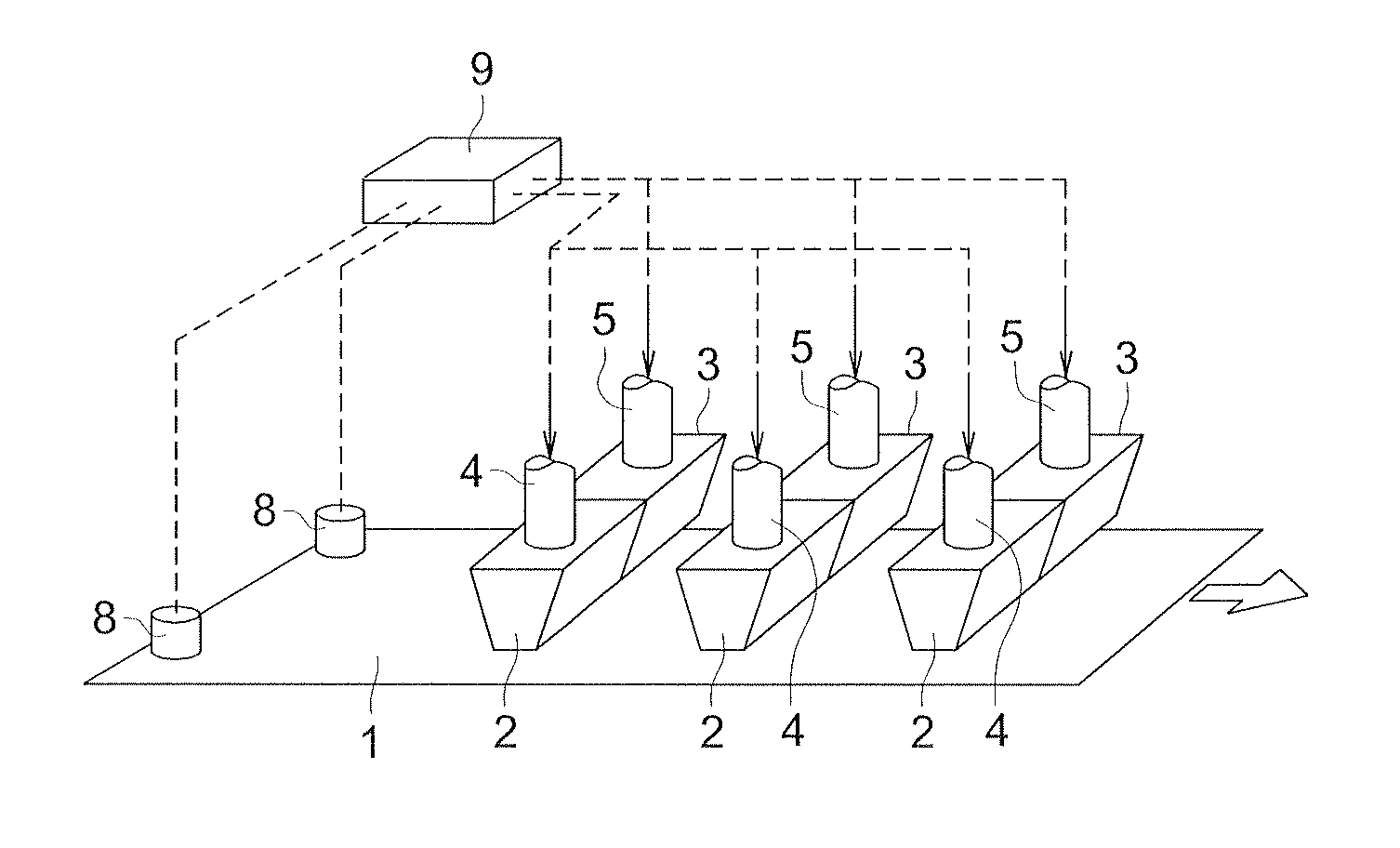
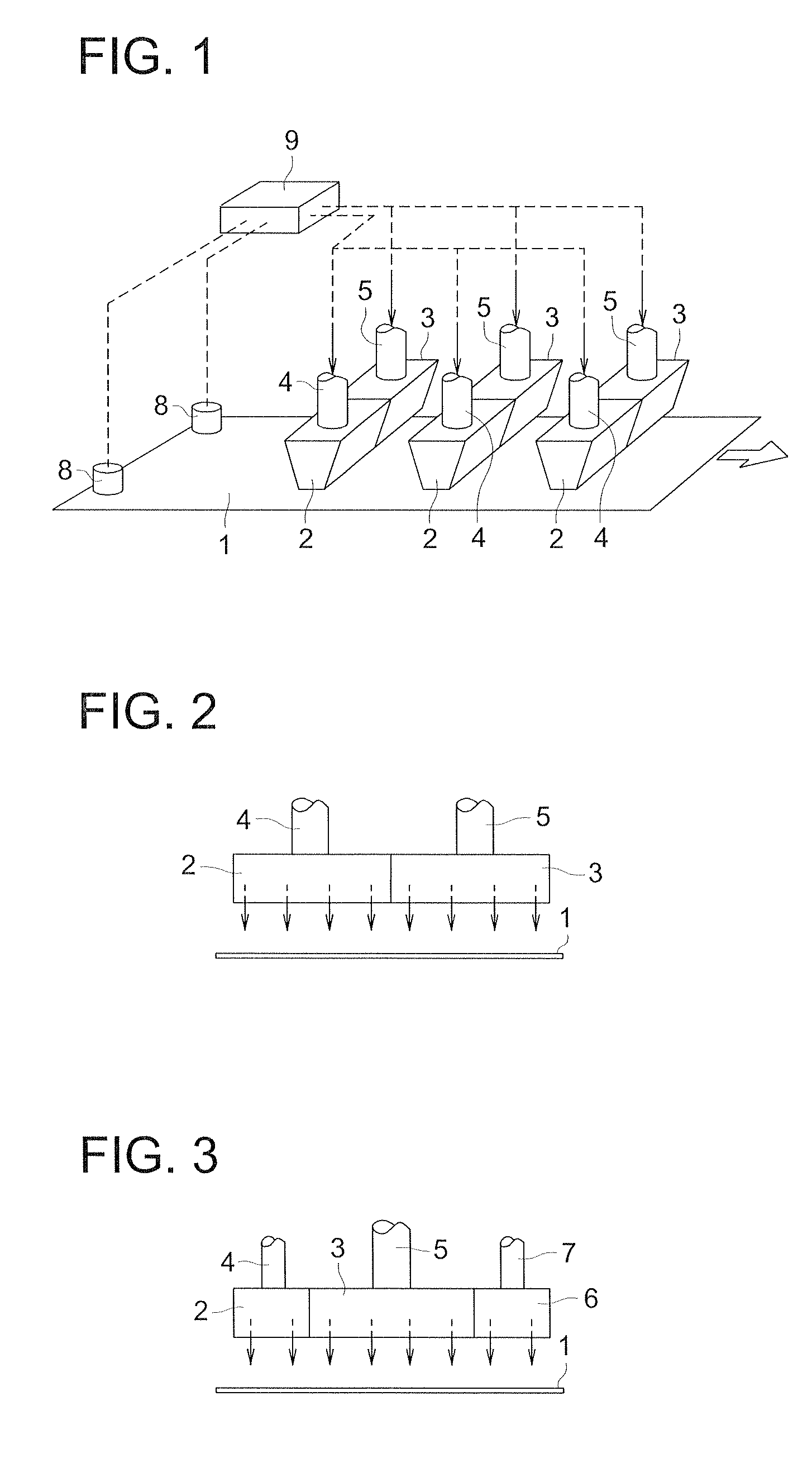
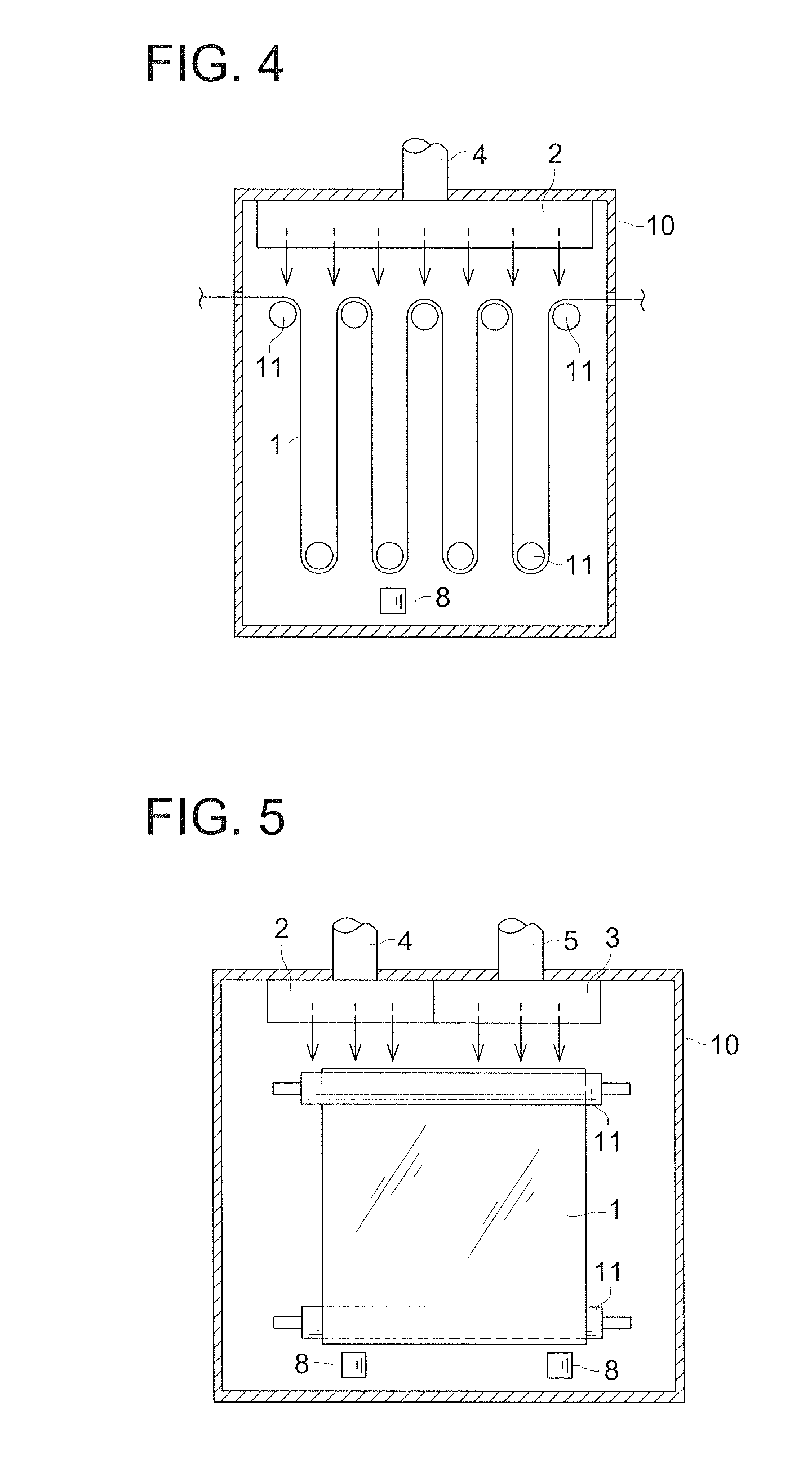
[0284] In Example 2, the cellulose triacetate propionate film was produced similarly to the manner of Example 1. The difference in the manner from that used in the Example 1 is that the apparatus shown in FIGS. 6 and 7 was used to adjust the velocity of the hot air (dry air)—not the temperature of the hot air (dry air). A position-variable baffle plate 12 was installed close to the air outlet 2a of the hot air spraying header 2 to adjust the velocity of a dry air.

[0285] As described above, according to the Example 3 of the present invention, the solution-casting film-forming apparatus for embodying the method of the present invention comprises, in the drying zone, right and left headers 2 and 3 provided side by side along the lateral direction of the conveyed film and for spraying hot airs with different air velocities; and film thickness measuring sensors 8, 8 (refer FIG. 1) for measuring thicknesses of the conveyed film. The velocity of the hot airs are adjusted in response to th...


PUM

PropertyMeasurementUnit
thicknessaaaaaaaaaa
visible light transmittanceaaaaaaaaaa

Abstract

An optical film manufacturing method, including steps of: casting a dope in which a thermoplastic resin is dissolved in a solvent, on a support so as to form a web; peeling and conveying the web from the support; measuring a physical property of the conveyed web at plural positions along a lateral direction of the web and obtaining a deviation among plural measurement values of the physical property at the plural positions: and drying the web by adjusting drying conditions at the plural positions to differ in accordance with the deviation.

Description

[0001] This application is based on Japanese Patent Application No. 2005-304567 filed on Oct. 19, 2005, in Japanese Patent Office, the entire content of which is hereby incorporated by reference. BACKGROUND OF THE INVENTION [0002] The present invention relates to an optical film manufacturing method and an optical film manufacturing method for manufacturing an optical film used in various forms of display apparatuses such as a liquid crystal display apparatus (LCD) or organic electroluminescent display, particularly to an optical film having a birefringence and used for a polarizing plate protecting film used in these display apparatuses and a retardation film. [0003] Generally, a liquid crystal display apparatus is basically arranged in such a way that a polarizing plate is provided on both sides of the liquid crystal cell. The polarizing plate permits the passage of only the light on the plane of polarization in a predetermined direction. It plays a major role in the liquid crysta...

Claims


Application Information

Patent Timeline
Patent Type & Authority Applications(United States)
IPC IPC(8): B29D11/00B29C47/34B29C47/88B29C48/355B29C48/92
CPCB29C41/28B29C2037/90B29D11/00B29K2001/00B29K2001/12B29C48/92B29C2948/92171B29C2948/92447B29C2948/92523B29C2948/92666B29C41/24B29C41/46B29C41/52B29L2011/00
Inventor NAGASHIMA, KATSUSUKE
Owner KONICA MINOLTA OPTO
Why Eureka
Try Eureka