Image display apparatus and control method thereof

a technology of image display and control method, which is applied in the direction of discharge tube main electrodes, tubes with screens, instruments, etc., can solve the problems of low response speed of hot cathode devices, high response speed of cold cathode devices, and hardly arisen heat fusion of substrates

Inactive Publication Date: 2007-04-19
CANON KK
View PDF4 Cites 5 Cited by
  • Summary
  • Abstract
  • Description
  • Claims
  • Application Information

AI Technical Summary

Benefits of technology

[0028] The interior of the airtight container is kept at a vacuum of about 10−6 Torr. As the display area of the image display apparatus increases, demand is arising for any means for preventing deformation or destruction of the rear and face plates 3115 and 3117 caused by the difference between inner and outer pressures of the airtight container. If destruction is prevented by making the rear and facing plates 3115 and 3117 thick, this increases the weight of the image display apparatus, and generates distortion and parallax of an image when viewed diagonally. For this reason, the display panel in FIG. 31 adopts a structure support (to be referred to as a spacer or rib) 3120 which is made of a relatively thin glass plate and supports the airtight container against the atmospheric pressure. This spacer generally keeps the interval between the substrate 3111 having the multi electron source and the face plate 3117 having the fluorescent film 3118 at sub-mm to several mm, thereby keeping the interior of the airtight container in a high-vacuum state, as described above.
[0039] Since the arrangement of this aspect adopts the detection means, the state of the display panel can be detected to control the image display apparatus at good timing. In particular, the present invention can preferably prolong the service life of the display panel under this control and suppress deterioration of characteristics to allow using the display panel for a long time. From this viewpoint, a desirable detection device is performed in a non-destructive condition in order to detect the state of the display panel.
[0058] Control of the image display apparatus in accordance with the state of the display panel is control of transferring information for prompting an information receiving person to control the image display apparatus. The information receiving person, e.g., the user of the image display apparatus or the maintenance personnel of the image display apparatus can control to suppress the progress of the abnormality in accordance with the transferred information.

Problems solved by technology

Even if a large number of devices are arranged on a substrate at a high density, problems such as heat fusion of the substrate hardly arise.
In addition, the response speed of the cold cathode device is high, while the response speed of the hot cathode device is low because it operates upon heating by a heater.

Method used


Image

  • Image display apparatus and control method thereof
  • Image display apparatus and control method thereof
  • Image display apparatus and control method thereof

Examples


first embodiment

[0115] As the first embodiment of the present invention, a display panel using an electron-emitting device and a driving circuit for the display panel will be described in detail. The display panel of the first embodiment has the same structure as shown in FIG. 31, and a detailed description thereof will be omitted.

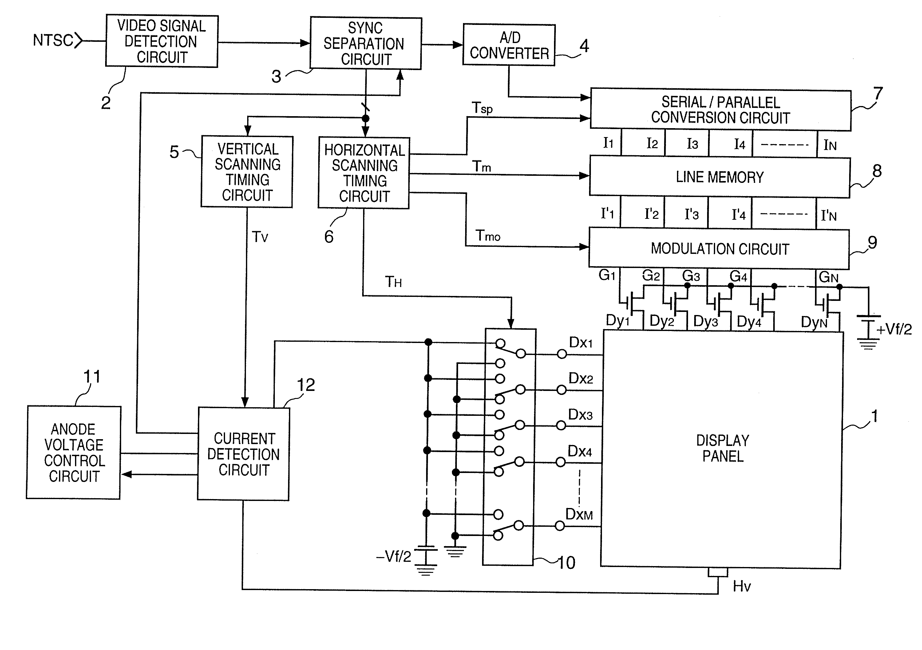
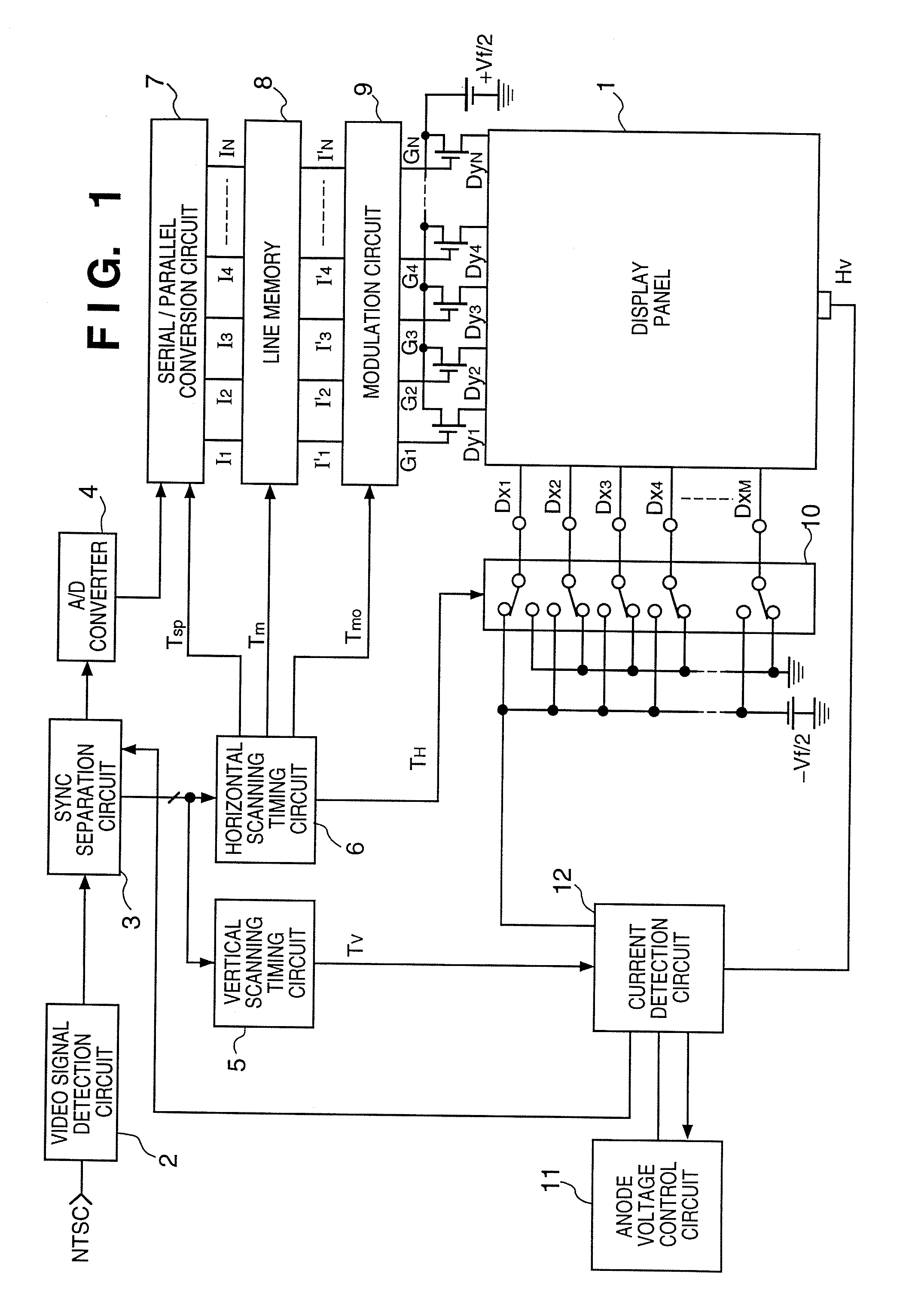
[0116]FIG. 1 is a block diagram showing the arrangement of a driving circuit for the display panel of an image display apparatus according to the first embodiment.

[0117] In FIG. 1, reference numeral 1 denotes a display panel using a cold cathode device (electron-emitting device: to be described in detail later). An external video signal (e.g., an NTSC signal) is input to a video signal detection circuit 2 for detecting a video signal, and an output from the video signal detection circuit 2 is input to a sync separation circuit 3 for separating and outputting a video signal and horizontal and vertical sync signals.

[0118] The video signal separated by the sync separation...

second embodiment

[0133]FIG. 3 is a perspective view of a display panel 1a according to the second embodiment of the present invention where part of the display panel 1a is removed for showing the internal structure of the panel.

[0134] The display panel of the second embodiment has almost the same structure as the display panel shown in FIG. 31 except that a fluorescent substance 3118 and a metal back 3119 are uniformly divided on a face plate 3117, as represented by fluorescent plates 13 in FIG. 3. In addition, the second embodiment uses a substrate 3111 as a rear plate without using any rear plate 3115. The same reference numerals as in FIG. 31 denote the same parts, and a description thereof will be omitted.

[0135] The fluorescent plates 13 are used to individually detect local variations in spacer current inside the display panel 1a, and enable detection of a partial anode current or the like, compared to the first embodiment. The second embodiment employs 10 divided fluorescent plates 13, and t...

third embodiment

[0144]FIG. 5 is a perspective view of a display panel 1b according to the third embodiment of the present invention. In FIG. 5, part of the panel is removed for showing the internal structure of the panel.

[0145] In the third embodiment, dummy spacers 16 are formed from the same material by the same manufacturing method as spacers 3120 on a dummy wiring 17 formed along the column wiring in the display panel of the second embodiment shown in FIG. 3. Similar to the second embodiment, the dummy spacers 16 respectively correspond to a plurality of fluorescent plates 13 each including a fluorescent substance and metal back. The dummy spacers 16 are equal in number to 10 divided fluorescent plates 13.

[0146] The dummy wiring 17 is formed at a position independently of row and column wirings connecting electron-emitting devices 3112 laid out in a matrix.

[0147] The first and second embodiments detect a current value flowing through the spacer itself in the display panel, whereas the third ...


PUM


Abstract

An image display apparatus includes a display panel having an electron source, an acceleration electrode for accelerating electrons emitted from the electron source and phosphors for emitting light by collision of electrons accelerated by the acceleration electrode, and a detector for detecting a current flowing through the acceleration electrode during a non-display period. In addition, a controller is provided to decrease the luminance level, stop display driving or transmit warning information when the current detected becomes more than a predetermined value.

Description

BACKGROUND OF THE INVENTION [0001] 1. Field of the Invention [0002] The present invention relates to an image display apparatus which displays an image by the emitted electrons, and control method of the apparatuses. [0003] 2. Description of the Related Art [0004] Conventionally, two types of devices, namely hot and cold cathode devices, are known as electron-emitting devices. Known examples of the cold cathode devices are surface-conduction type emission devices, field emission type electron-emitting devices (to be referred to as FE type electron-emitting devices hereinafter), and metal / insulator / metal type electron-emitting devices (to be referred to as MIM type electron-emitting devices hereinafter). [0005] Known examples of the FE type electron-emitting devices are described in W. P. Dyke and W. W. Dolan, “Field emission”, Advance in Electron Physics, 8, 89 (1956) and C. A. Spindt, “Physical properties of thin-film field emission cathodes with molybdenium cones”, J. Appl. Phys.,...

Claims


Application Information

Patent Timeline
Patent Type & Authority Applications(United States)
IPC IPC(8): G09G3/22G06F3/147G09G3/20H01J29/04H01J31/12
CPCG06F3/147G09G3/006G09G3/2014G09G3/22G09G2300/043G09G2300/0443G09G2300/0452G09G2300/06G09G2310/0218G09G2310/0267G09G2310/027G09G2310/0275G09G2320/0285G09G2320/029G09G2320/043G09G2330/02G09G2330/021G09G2330/028G09G2330/04G09G2330/045H01J31/127H01J2201/3165H01J1/30
Inventor KUNO, MITSUTOSHISAGANO, OSAMUFUJII, AKIRA
Owner CANON KK
Why Eureka
Try Eureka