Method of detecting faults using graduated fault detection levels

a fault detection and fault technology, applied in the direction of alarms, instruments, arrangements responsive to excess voltage, etc., can solve the problems of system that relies on the absence of current in an open conductor to achieve improper readings, short duration current spikes in electrical power distribution systems, and low detection accuracy

Active Publication Date: 2007-04-19
SCHWEITZER ENGINEERING LABORATORIES
View PDF71 Cites 32 Cited by
  • Summary
  • Abstract
  • Description
  • Claims
  • Application Information

AI Technical Summary

Benefits of technology

[0012] The present invention achieves its objectives through the use of one or more digital fault indication curves. In one embodiment of the invention, a faulted circuit indicator stores a collection of fault indication curves within a persistent memory component. Each fault indication curve comprises a plurality of associated fault current levels and fault times stored. In addition, the faulted circuit indicator comprises a current acquisition circuit adapted to monitor current within a conductor, and a Digital to Analog Converter (DAC) coupled to an analog comparator circuit. The current acquisition circuit is also coupled to the comparator, which outputs a digital signal indicating the detection of instantaneous fault current in a form usable by a processor. The processor, which is stored within the same housing as the rest of the components, controls the DAC output, and determines if the current within the conductor is outside the range allowed by the presently selected fault indication curve by monitoring the output of the analog comparator; i.e.; whether the current exceeds one of the fault current levels for its associated fault time. If so, the faulted circuit indicator displays a fault condition.
[0013] In a further refinement of this embodiment, the persistent memory component contains a plurality of fault indication curves, and the processor selects an appropriate fault indication curve based on the average current level within the monitored conductor. The average current level may be determined by a dedicated analog circuit, or by the processor maintaining an average within its memory.

Problems solved by technology

Electrical power distribution systems are susceptible to current spikes of short duration, which may be caused, for instance, by switching on large inductive loads.
However, strict adherence to a delayed trip algorithm can cause a faulted circuit indicator to not indicate a fault when a very large fault current occurs for a brief period of time, and then dissipates.
This situation can result from the occurrence of a fault sufficiently large to cause the system's protection devices to operate (i.e.; a fuse to open, etc.), which results in the monitored conductor's current falling to zero.
However, any system that relies on the absence of current in an open conductor is susceptible to improper readings due to the presence of backfeed, or current flowing through a conductor that has been disconnected from the electrical power distribution system.
The circuit also has a large magnitude limit, above which any duration of fault current will be interepreted as a fault.
This circuit can be configured to closely match specific fuse elements, however it is limited in application to a variety of fuse elements or system protection devices.

Method used


Image

  • Method of detecting faults using graduated fault detection levels
  • Method of detecting faults using graduated fault detection levels
  • Method of detecting faults using graduated fault detection levels

Examples


Embodiment Construction

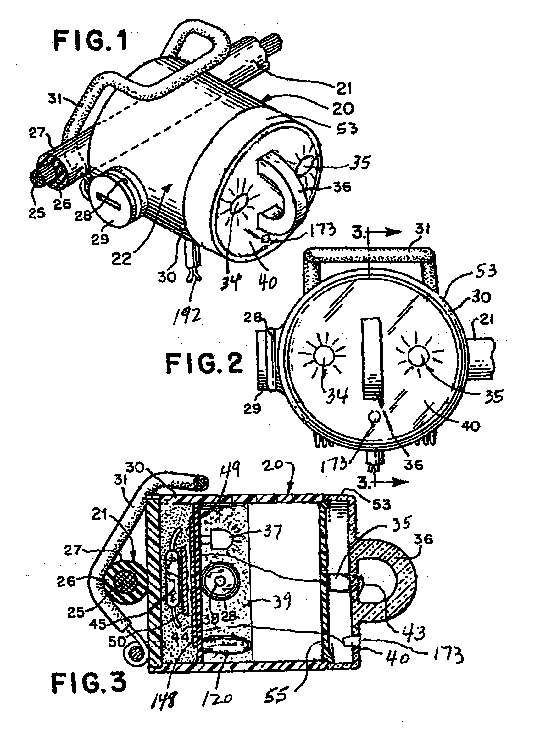
[0025] Referring to the Figures, and particularly to FIG. 1, a faulted circuit indicator, generally designated 20, is constructed in accordance with the invention. Fault indicator 20 indicates fault currents in an electrical feeder or distribution cable, generally designated 21, and includes a circuit module, generally designated 22. In accordance with conventional practice, circuit module 22 is attached to the outer surface of the cable 21, which may include a central conductor 25, a concentric insulating layer 26 and an electrically grounded rubber outer sheath 27.

[0026] Circuit module 22 includes a housing 30 (FIG. 2) that contains electronic circuitry for sensing and responding to fault currents in cable 21. A clamp assembly 31 attaches the module to a monitored conductor, such as cable 21. The structure and operation of this circuitry is discussed below. An eye 36 on an end cap 53 may be provided to allow use of a conventional hot stick during installation or removal of fault ...


PUM


Abstract

A faulted circuit indicator utilizes digitized fault indication curves to determine if a fault has occurred in a monitored conductor. Fault indication curves are intended to be similar to trip curves of common power protection devices, and consist of a plurality of associated fault current levels and fault times. The faulted circuit indicator only displays a fault when the current within the monitored conductor exceeds one of the fault current levels for its associated fault time. This results in more accurate fault detection through the ability to distinguish between small and large amplitude faults coupled with the flexability of a fault indicator suitable for use on many different power systems.

Description

CROSS-REFERENCE TO RELATED APPLICATIONS [0001] This reference claims priority to provisional application 60 / 727,765, filed Oct. 18, 2005.FIELD OF THE INVENTION [0002] The present invention relates generally to apparatus, systems, and methods for sensing current in electrical power distribution systems, and more particularly to apparatus, systems, and methods for reliably indicating faults in electrical power distribution systems susceptible to current spikes of short duration during normal operation of the electrical power distribution system. DESCRIPTION OF THE PRIOR ART [0003] Various types of self-powered fault indicators have been constructed for detecting electrical faults in electrical power distribution systems, including clamp-on type fault indicators, which clamp directly over cables in the systems and derive their operating power from inductive and / or capacitive coupling to the monitored conductor; and test point type fault indicators, which are mounted on test points pres...

Claims


Application Information

Patent Timeline
Patent Type & Authority Applications(United States)
IPC IPC(8): H02H3/20
CPCH02H3/04
Inventor SWARTZENDRUBER, RYAN W.FEIGHT, LAURENCE VIRGILSALEWSKE, TYSON J.
Owner SCHWEITZER ENGINEERING LABORATORIES
Why Eureka
Try Eureka