Optical fiber splice enclosure

a fiber optic cable and enclosure technology, applied in the field of fiber optics, can solve the problems of insufficient strength of fiber optic cables to support their own weight between the poles, and not an effective way to provide distributive customer access without extensive fiber splicing cost, and achieve the effect of reducing the cost of fiber cable access, cost-effective, and improving the speed of network deploymen

Inactive Publication Date: 2007-04-19
AFL COMM LLC
View PDF3 Cites 29 Cited by
  • Summary
  • Abstract
  • Description
  • Claims
  • Application Information

AI Technical Summary

Benefits of technology

[0019] Features of the invention include lowering the cost of fiber cable access due to utilizing less cable, not splicing un-needed fibers at a given access point and improving the speed of a network deployment by not requiring relocation of extra cable to provide fiber to an access node. This results in a cost effective solution that saves both time and money.

Problems solved by technology

Some fiber optic cables do not have sufficient strength to support their own weight between the poles.
In aerial fiber optic cable systems, that utilize Loose Tube fiber optic cable, All-Dielectric Self-Supporting (ADSS) fiber optic cable or Integrated Messenger (IM) fiber optic cable, there is not an effective way to provide a distributive customer access without having extensive fiber splicing cost.
In ADSS an IM type cables, however, there is no external supporting messenger, and in various networks, there is a need to quickly access the fibers without having to remove cable from storage devices to create enough slack to splice the optical fibers.

Method used


Image

  • Optical fiber splice enclosure
  • Optical fiber splice enclosure
  • Optical fiber splice enclosure

Examples


Embodiment Construction

[0029] The following description of illustrative, non-limiting embodiments of the apparatus discloses specific configurations and components. However, the embodiments are merely examples of the present invention and, thus, the specific features described below are merely used to more easily describe such embodiments and to provide an overall understanding of the present invention. Accordingly, one skilled in the art will readily recognize that the present invention is not limited to the specific embodiments described below. Furthermore, the descriptions of various configurations, components, processes and operations of the embodiments that are known to one skilled in the art are omitted for the sake of clarity and brevity.

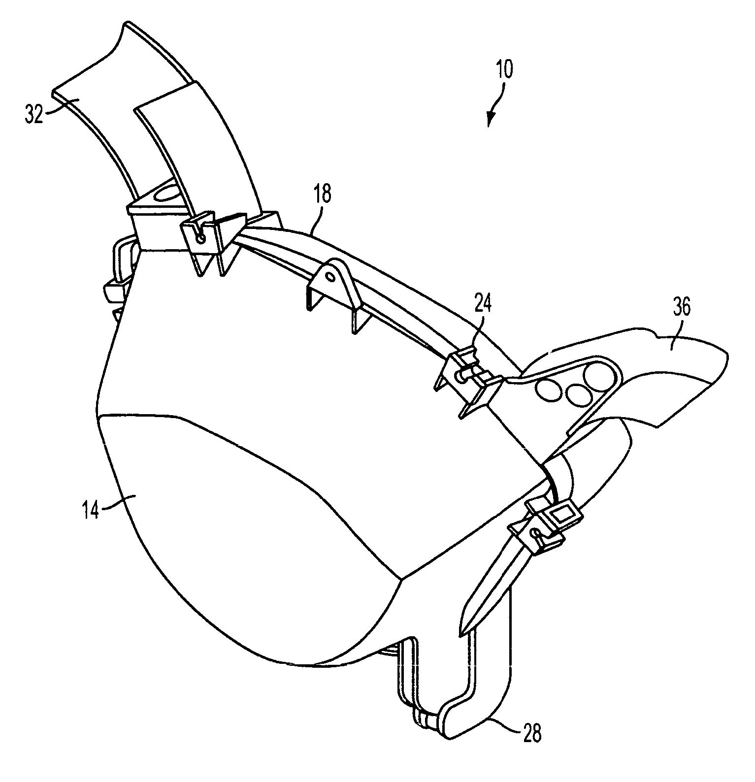
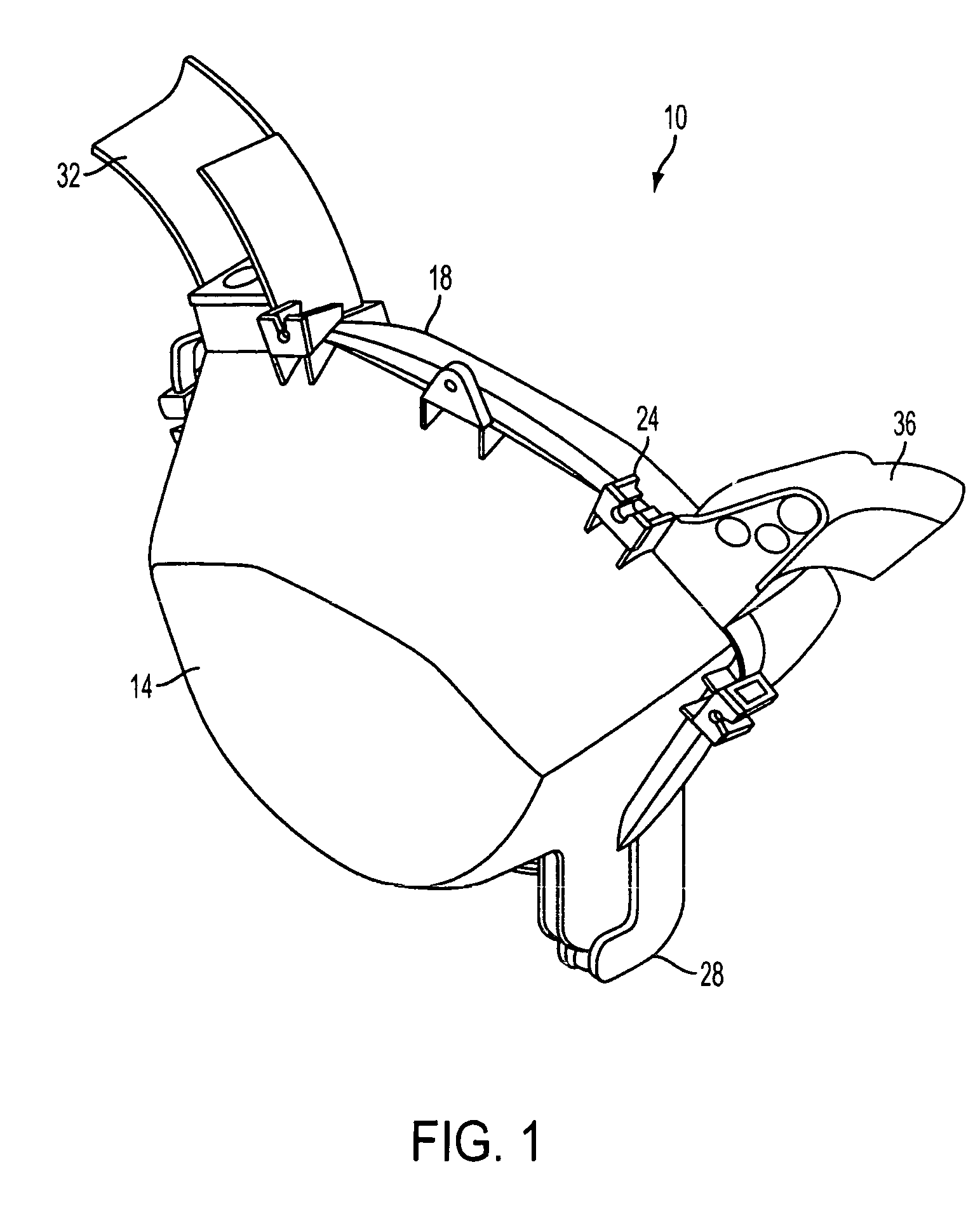
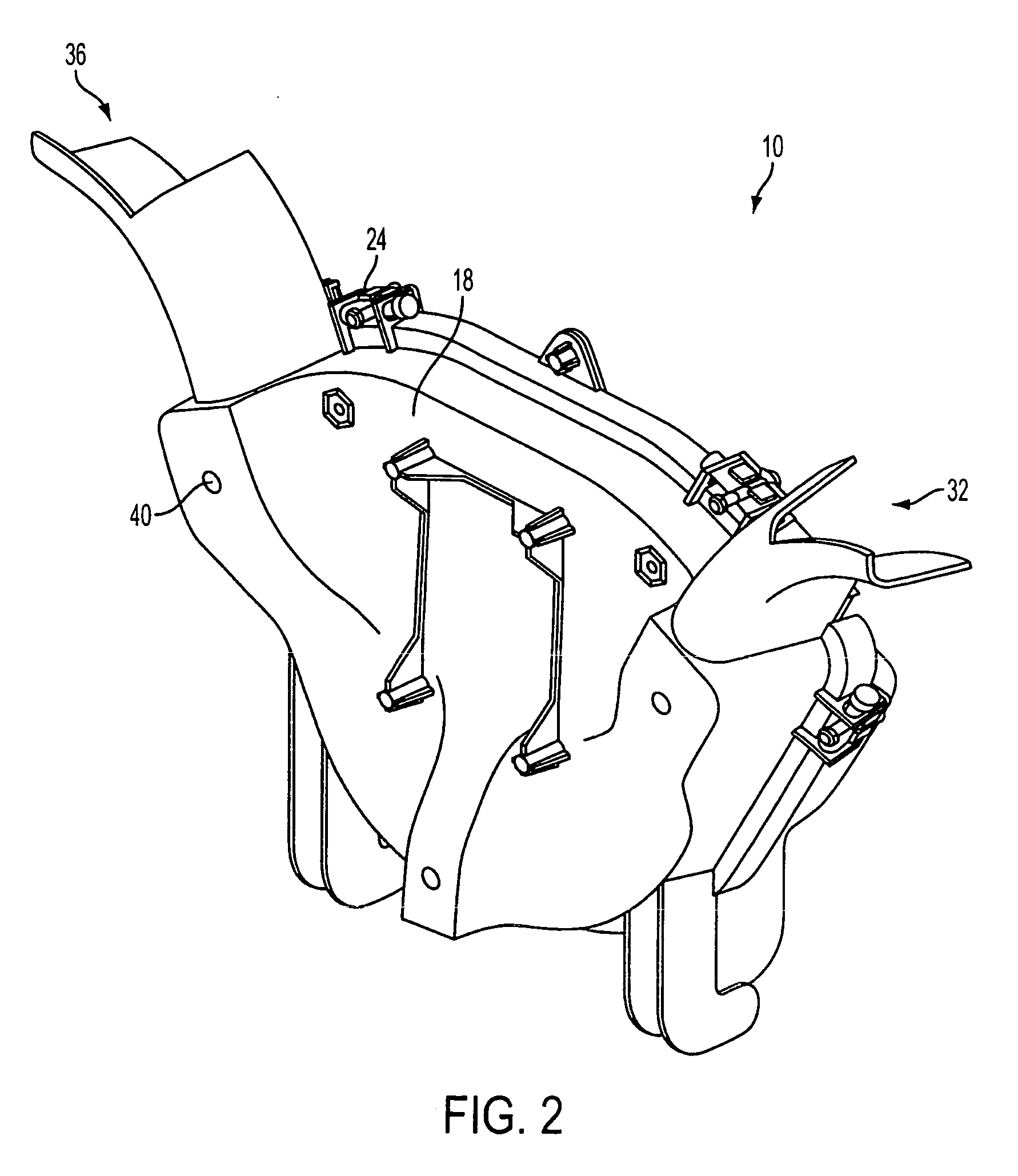
[0030]FIGS. 1 and 2 depict an exemplary fiber optic closure 10 used for splicing together a plurality of optical fibers and / or fiber optic cables. The optical fiber closure comprises a housing cover 14 and housing base 18 which are mated such that the closure 10 m...


PUM


Abstract

A fiber optic housing including a base and a cover pivotally to the base. A first guide is provided through which a fiber optic cable enters the housing, along with a second guide through which the fiber optic cable exits the housing. The cover is moveable between an open and closed position, such that the cover forms a horizontally extending tray when in the open position. A splice tray mounting portion is provided within the housing with at least one splice tray. The closure is configured such that a loop of slack buffer tubes is wound around an inner circumferential area of the housing.

Description

CROSS REFERENCE TO RELATED APPLICATION [0001] This application claims the benefit of provisional patent application Ser. No. 60 / 698,986 filed Jul. 14, 2005, entitled “Optical Fiber Splice Enclosure.”BACKGROUND OF INVENTION [0002] 1. Field of Invention [0003] The present invention relates generally to the field of fiber optics and, more particularly, to an optical fiber splice enclosure used in the [0004] 2. Background of the Invention [0005] Optical fiber systems are becoming widely used to transmit large volumes of data through fiber optic cables over relatively long distances. Fiber optic cables are often suspended between poles, towers, or other above-ground structures. Some fiber optic cables do not have sufficient strength to support their own weight between the poles. In this case, a support strand may be suspended between the poles and along the cable. Alternatively, some fiber optic cables enclose a cable wire messenger wire in an outer sheath of the cable to provide support...

Claims


Application Information

Patent Timeline
Patent Type & Authority Applications(United States)
IPC IPC(8): G02B6/00
CPCG02B6/445
Inventor DOBBINS, PATRICK E.NIEVES, ANTHONY L.NARSIDANI, FIROZ
Owner AFL COMM LLC
Why Eureka
Try Eureka