Microfluidic device utilizing magnetohydrodynamics and method for fabrication thereof

a microfluidic device and magnetohydrodynamic technology, applied in the direction of positive displacement liquid engines, laboratory glassware, inking apparatus, etc., can solve the problems of diffusion predominance, difficult mixing with extremely small volumes, and small samples that pose challenging problems in analyzing their content, etc., to achieve constant magnetic fields, easy reversible pumping methods, and small volum

Inactive Publication Date: 2007-04-19
THE BOARD OF TRUSTEES OF THE UNIV OF ARKANSAS
View PDF17 Cites 7 Cited by
  • Summary
  • Abstract
  • Description
  • Claims
  • Application Information

AI Technical Summary

Benefits of technology

[0048] The invention disclosed here is a new method of microfluidic propulsion and a set of devices that promises to solve many of the problems that other existing microfluidic methods suffer from. This new approach is capable of moving small volumes of fluids through a channel, in either direction, without valves. These devices may be constructed from a variety of materials and use voltages that are in the millivolt to volt range. In addition, this invention utilizes relatively small, constant magnetic fields that can be provided by small permanent magnets. The method disclosed is effective on extremely small samples, less than 100 picoliters. MHD is also a readily reversible method of pumping. These characteristics make this invention especially suitable for use in LOC technology. It may be used for chemical analysis of very small samples, such as those common in forensics, DNA and medical testing.
[0049] In order to avoid water electrolysis, chemicals that are highly susceptible to reduction / oxidation are added to the solution prior to its addition to the microfluidic system. These reduction / oxidation (redox) chemicals serve as “ferries” transporting electrons from the anode to the chathode. Once oxidized at the cathode, they return to the anode where they are once again reduced. This cycle is repeated many times. By using redox chemicals in the fluid as electron transporters, electrolysis of water is avoided. The redox species in the solution are propelled in a direction perpendicular to both the electric and magnetic fields. This movement of the redox species causes the entire solution to flow in the same direction. This constitutes a significant improvement over existing microfluidic technology.
[0051] Mixing is generally difficult with extremely small volumes. Sample preparation and assays, such as immunoassays and DNA analysis, involve combining of reagents in very small amounts. Small samples pose challenging problems in analyzing their content, since signal of small volumes is generally small or requires special equipment to achieve high sensitivity. Some chemical detection methods, such as electrochemical detection, have a signal that depends on how fast the molecular species move past the detector or a modified surface which captures the analyte. The inability to mix extremely small volumes allows diffusion to predominate and significantly reduces the accuracy of small sample analysis. The invention disclosed herein allows mixing of such small samples and can significantly improve the accuracy of small sample analysis. Methods of mixing extremely small samples have eluded scientists for years. In the present invention, relatively high concentration of current carrying species, such as redox chemicals, nanoparticles, or the like are usually used. This guarantees the inhibition of water electrolysis. The current carrying species carries the entire current. This also rapidly and effectively mixes samples as small as a hundred picoliters. The rapid movement of the redox species or nanoparticles mixes the solution.
[0052] Another advantage provided by the present invention is that a wide variety of redox chemicals may be used. It may be desirable to use MHD microfluidic technology to analyze chemicals that react with various redox compounds. In such situations, a different, non-reactive redox chemical, nanoparticle or the like may be employed instead without any adverse effects. This ability to choose from a wide range of suitable current carrying species makes the present invention more practical and more adaptable than other microfluidic pumping methods. It is also possible that small scale, portable LOC devices may be exposed to various extreme conditions. Some conditions such as extreme pressures, heat or cold may have an adverse effect on certain redox chemicals. Again, in these situations specific redox chemicals may be employed that best suit a given situation.
[0053] The present invention also allows the pumping action of the MHD microfluidics channel to be separated from the analyte solution. A hydrophobic solution having a current carrying species may be used to push an aqueous solution through a microfluidic channel. The two solutions will not mix together. This provides many advantages. Many analytes may react with redox species or nanoparticles to form different compounds. This will decrease the accuracy of any measurements of the analyte. Current carrying species may disrupt the method of detection of the analyte, causing false positives or false negatives. By separating the analyte solution from the pumping solution, the analyte remains unaffected.
[0055] The magnetohydrodynamic microfluidic systems disclosed herein are especially suited for the formation of microfluidic assay structures that allow the performance of chemical detection assays within very small chips. Reduction / oxidation assays, ELISA's polynucleotide hybridizations and other immobilization assays may all be performed within microfluidic assay structures. These assays, because of their electrochemical nature and small volume, are fast, reliable, sensitive and easily transported.

Problems solved by technology

Mixing is generally difficult with extremely small volumes.
Small samples pose challenging problems in analyzing their content, since signal of small volumes is generally small or requires special equipment to achieve high sensitivity.
The inability to mix extremely small volumes allows diffusion to predominate and significantly reduces the accuracy of small sample analysis.
Methods of mixing extremely small samples have eluded scientists for years.

Method used


Image

  • Microfluidic device utilizing magnetohydrodynamics and method for fabrication thereof
  • Microfluidic device utilizing magnetohydrodynamics and method for fabrication thereof
  • Microfluidic device utilizing magnetohydrodynamics and method for fabrication thereof

Examples


Embodiment Construction

[0059] The embodiments discussed herein are merely illustrative of specific manners in which to make and use the invention and are not to be interpreted as limiting the scope of the instant invention.

[0060] While the invention has been described with a certain degree of particularity, it is to be noted that many modifications may be made in the details of the invention's construction and the arrangement of its components without departing from the spirit and scope of this disclosure. It is understood that the invention is not limited to the embodiments set forth herein for purposes of exemplification.

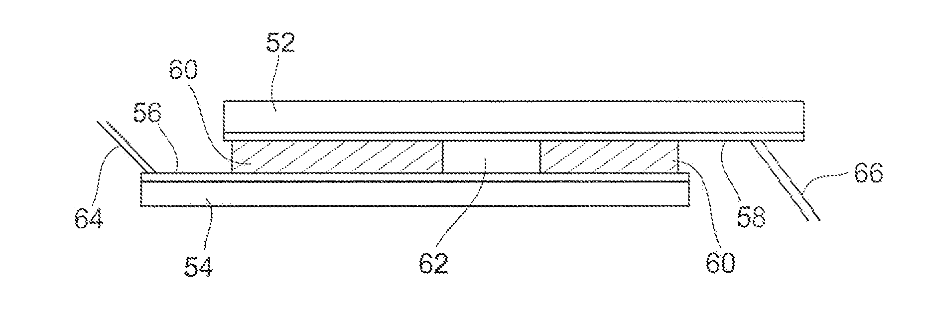
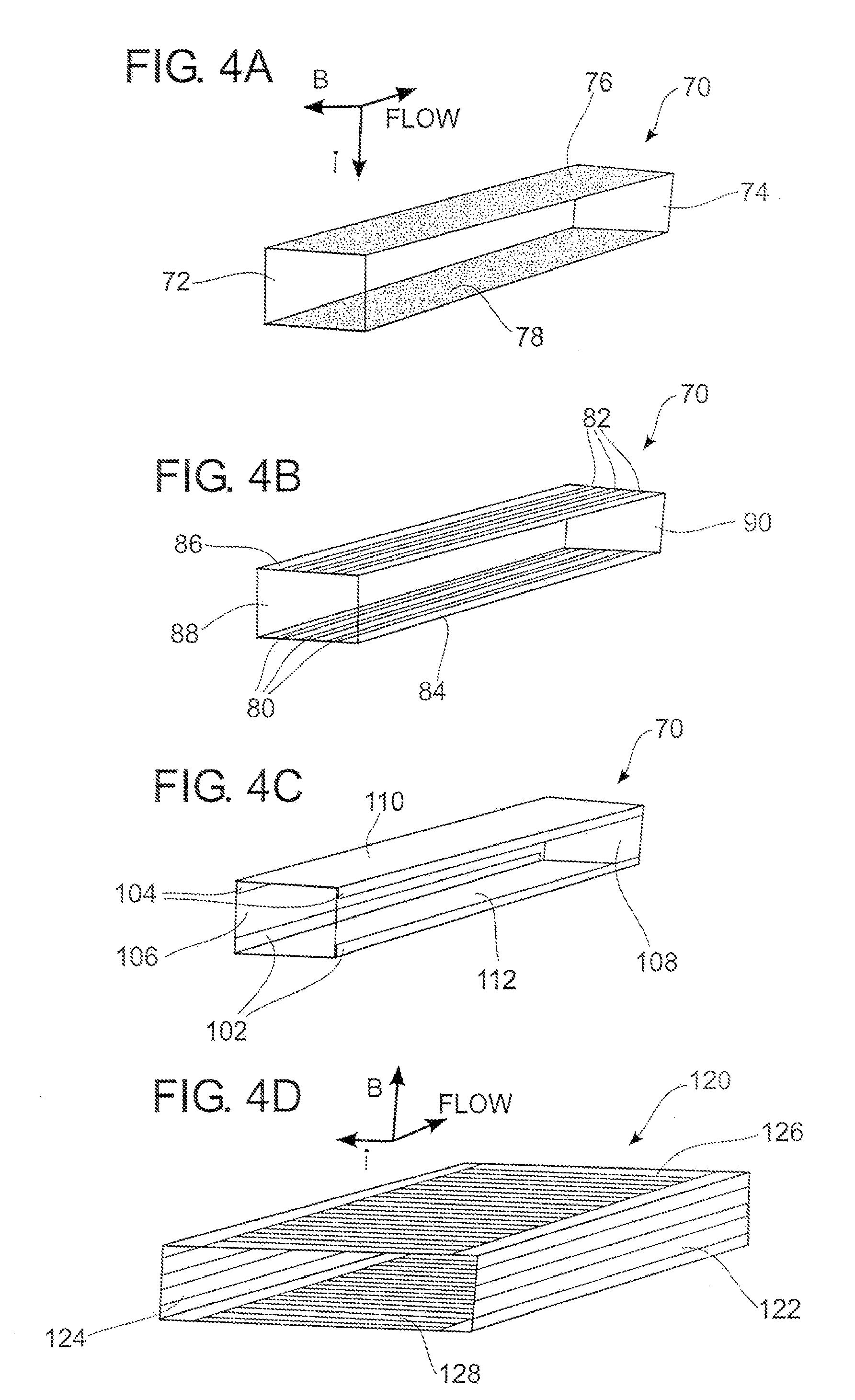
[0061] MHD Lorentz forces have been known to physicists for almost 200 years. It involves 3 physical fields all perpendicular to one another. The flow or velocity field is aligned perpendicular to both the magnetic and electric fields which are also perpendicular to one another. Manipulation of any two of these fields results in a change in the third one. In the present invention, an ...


PUM

PropertyMeasurementUnit
widthaaaaaaaaaa
widthaaaaaaaaaa
widthaaaaaaaaaa

Abstract

Microfluidic channels utilizing magnetohydrodynamics are used to pump very small volumes of solution. The channels have electrodes along the walls and a current carrying species within a solution carries current through the solution. The combination of the electric and magnetic fields causes the solution to flow through the channel.

Description

CROSS-REFERENCE TO RELATED APPLICATIONS [0001] This application is a divisional of U.S. patent application Ser. No. 10 / 317,777, filed Dec. 22, 2002 and claims priority to U.S. patent application Ser. No. 10 / 026,748, now U.S. Pat. No. 6,733,244, filed Dec. 19, 2001 and claims priority to U.S. Provisional Application Ser. No. 60 / 257,331, filed Dec. 20, 2000 and claims priority to U.S. Provisional Application Ser. No. 60 / 278,275, filed Mar. 22, 2001 and claims priority to U.S. patent application Ser. No. 10 / 252,342, filed Sep. 23, 2002.BACKGROUND OF THE INVENTION [0002] 1. Field of the Invention [0003] The present invention relates to microfluidic devices. In particular, the present invention relates to the use of magnetohydrodynamics to propel or mix fluids within microfluidic structures. [0004] 2. Prior Art [0005] The field of microfluidics is growing rapidly. There is a strong desire to miniaturize chemical assays. A number of various technologies are currently being developed in an...

Claims


Application Information

Patent Timeline
Patent Type & Authority Applications(United States)
IPC IPC(8): F04B37/02
CPCB01F13/0077B82Y30/00B41J2202/04Y10T29/49236F04B19/006B01F33/3032
Inventor FAKUNLE, EYITAYO S.O.ARUMUGAM, PRABHU U.FRITSCH, INGRIDMINCY, JEFFREY ELBERTBARLOW, FRED D. IIIWANG, GANGQIANG
Owner THE BOARD OF TRUSTEES OF THE UNIV OF ARKANSAS
Why Eureka
Try Eureka