Microfluidics and small volume mixing based on redox magnetohydrodynamics methods

Inactive Publication Date: 2006-12-12
THE BOARD OF TRUSTEES OF THE UNIV OF ARKANSAS
View PDF13 Cites 37 Cited by
  • Summary
  • Abstract
  • Description
  • Claims
  • Application Information

AI Technical Summary

Benefits of technology

[0048]The invention disclosed here is a new method of microfluidic propulsion and a set of devices that promises to solve many of the problems that other existing microfluidic methods suffer from. This new approach is capable of moving small volumes of fluids through a channel, in either direction, without valves. These devices may be constructed from a variety of materials and use voltages that are in the millivolt to volt range. In addition, this inv

Problems solved by technology

High fluid flow becomes more difficult as microfluidic structures become smaller.
This is due to increased drag created by moving along the walls of the microfluidic structure.
However, this method has only achieved relatively slow flow rates.
In addition it is difficult to scale down to the microfluidic level of less than 500 micrometers.
It is impossible to change flow direction and is only effective on aqueous solutions.
Although flow is reversible, flow rate is very slow.
This technique also requires a relatively large power supply.
However, electrokinetics suffers from disadvantages.
In addition, this technology requires high voltage and can only achieve relatively slow flow rates.
Electrokinetics also will not work in the presence of air bubbles, which are common in microfluidic systems.
Another disadvantage is that electrokinetics is ineffective on organic fluids.
Like hydrophobic films, this method only works well on aqueous solutions.
Application of a strong current may also alter chemicals present in the solution, thereby decreasing the accuracy of any analyses.
Mechanical methods of pumping fluids through microstructures also poses several problems.
The mechanical methods usually require valves which can complicate fabrication and become clogged.
Complex mechanical devices, including many valves, are difficult to scale down to small sizes.
In addition, m

Method used


Image

  • Microfluidics and small volume mixing based on redox magnetohydrodynamics methods
  • Microfluidics and small volume mixing based on redox magnetohydrodynamics methods
  • Microfluidics and small volume mixing based on redox magnetohydrodynamics methods

Examples


Embodiment Construction

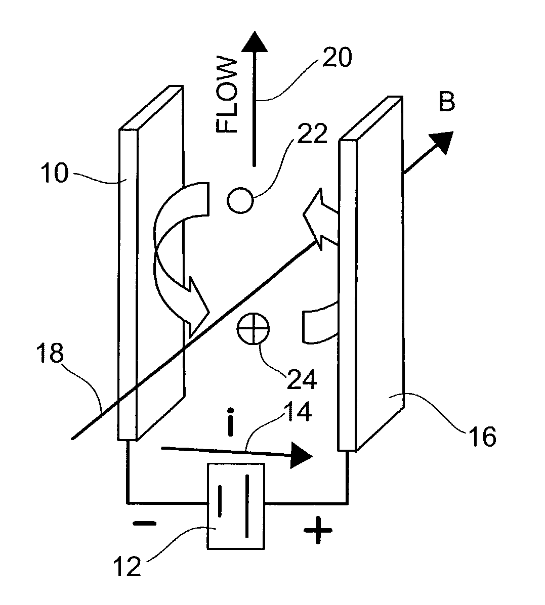
[0061]MHD Lorentz forces have been known to physicists for almost 200 years. It involves 3 physical fields all perpendicular to one another. The flow or velocity field is aligned perpendicular to both the magnetic and electric fields which are also perpendicular to one another. Manipulation of any two of these fields results in a change in the third one. In the present invention, an electric field and a magnetic field are applied to a channel both being perpendicular to the desired direction of flow.

[0062]MHD technology requires a relatively dense current in order to induce a significant rate of flow through the channel. At larger scales this is not practical. Small scale, microfluidic channels however, because of the unique properties associated with microelectrodes in close proximity to one another, allow for relatively high current densities. These may be combined with natural magnets. Magnetic fields on 0.4T or less may be adequate. Because natural magnets and a low amount of el...


PUM


Abstract

Microfluidic channels utilizing magnetohydrodynamics are used to pump very small volumes of solution. The channels have electrodes along the walls of the channel and a current carrying species within the solution carries the current through the solution. The electric field generated by the use of the current carrying species is perpendicular to a magnetic field applied to the channel. The combination of the electric and magnetic fields causes the solution to flow through the channel.

Description

CROSS-REFERENCE TO RELATED APPLICATIONS[0001]This application is a continuation-in-part of U.S. patent application Ser. No. 10 / 026,748, now U.S. Pat. No. 6,733,244 filed Dec. 19, 2001 and claims priority to U.S. Provisional Application Ser. No. 60 / 257,331, filed Dec. 20, 2000 and claims priority of U.S. Provisional Application Ser. No. 60 / 278,278, filed Mar. 22, 2001. This application is also a continuation-in-part of U.S. patent application Ser. No. 10 / 252,342, filed Sep. 23, 2002.BACKGROUND OF THE INVENTION[0002]1. Field of the Invention[0003]The present invention relates to microfluidic devices. In particular, the present invention relates to the use of magnetohydrodynamics to propel or mix fluids within microfluidic structures.[0004]2. Prior Art[0005]The field of microfluidics is growing rapidly. There is a strong desire to miniaturize chemical assays. A number of various technologies are currently being developed in an effort to develop what has become known as lab-on-a-chip (L...

Claims


Application Information

Patent Timeline
IPC IPC(8): F04B37/02F04F11/00B01F13/00B01L3/00F04B17/00F04B19/00F04F99/00
CPCB01F13/0077B01L3/502707B01L3/50273B01L3/502784B82Y30/00F04B17/00F04B19/006B01L2200/0605B01L2200/0647B01L2300/0887B01L2300/12B01L2400/0415B01L2400/043B01F33/3032
Inventor FRITSCH, INGRIDCARTER, CHRISTOPHER S.AGUILAR, ZORAIDA P.
Owner THE BOARD OF TRUSTEES OF THE UNIV OF ARKANSAS
Why Eureka
Try Eureka