Apparatus at a spinning preparation machine for the purpose of monitoring

a technology of preparation machine and apparatus, applied in mechanical treatment, alarms, instruments, etc., can solve problems such as electrical current interruption, sensor damage, and destructive measuremen

Inactive Publication Date: 2007-04-26
TRUETZSCHLER GMBH & CO KG
View PDF7 Cites 0 Cited by
  • Summary
  • Abstract
  • Description
  • Claims
  • Application Information

AI Technical Summary

Benefits of technology

[0011] According to the invention, the sensor is set closer to the roller than is the component lying opposite to the roller. In the event of contact with the rapidly rotating roller, the sensor is destroyed. When that happens, electrical transmission is cut and consequently electric current, for example to a control system, display or alarm device, switching device or the like, is interrupted. The sensor is constantly energised. If, for example, a cable, which runs parallel in the sensor to the roller, is destroyed by contact with a clothing, the circuit is interrupted and a signal is delivered. For the crash sensor, that constitutes a destructive measurement.
[0012] Advantageously, starting from the roller, the second spacing to the sensor is smaller than the spacing to the component. Advantageously, the sensor is immobile. Advantageously, the sensor is an electrically conductive component of the electric circuit. Advantageously, two lines are connected to the electrically conducting sensor. Advantageously, at least one electrically conductive element, for example wire, is integrated into the sensor. Advantageously, the sensor consists of plastics or the like in which an electrical conductor is integrated. Advantageously, the current line is passed through the sensor body. Advantageously, an electrically conducting wire (current line) is embedded into the sensor body. Advantageously, the sensor body has a conductive coating, a conductive cover or the like. Advantageously, the sensor is arranged in the vicinity of the roller. Advantageously, the sensor generates an electric signal change directly from any contact between the component and the roller. Advantageously, the signal change is fed to a control system. Advanta...

Problems solved by technology

In the event of contact with the rapidly rotating roller, the sensor is destroyed.
For the crash sensor, that constitutes a destructive measurement.
Advantageous...

Method used


Image

  • Apparatus at a spinning preparation machine for the purpose of monitoring
  • Apparatus at a spinning preparation machine for the purpose of monitoring
  • Apparatus at a spinning preparation machine for the purpose of monitoring

Examples


Embodiment Construction

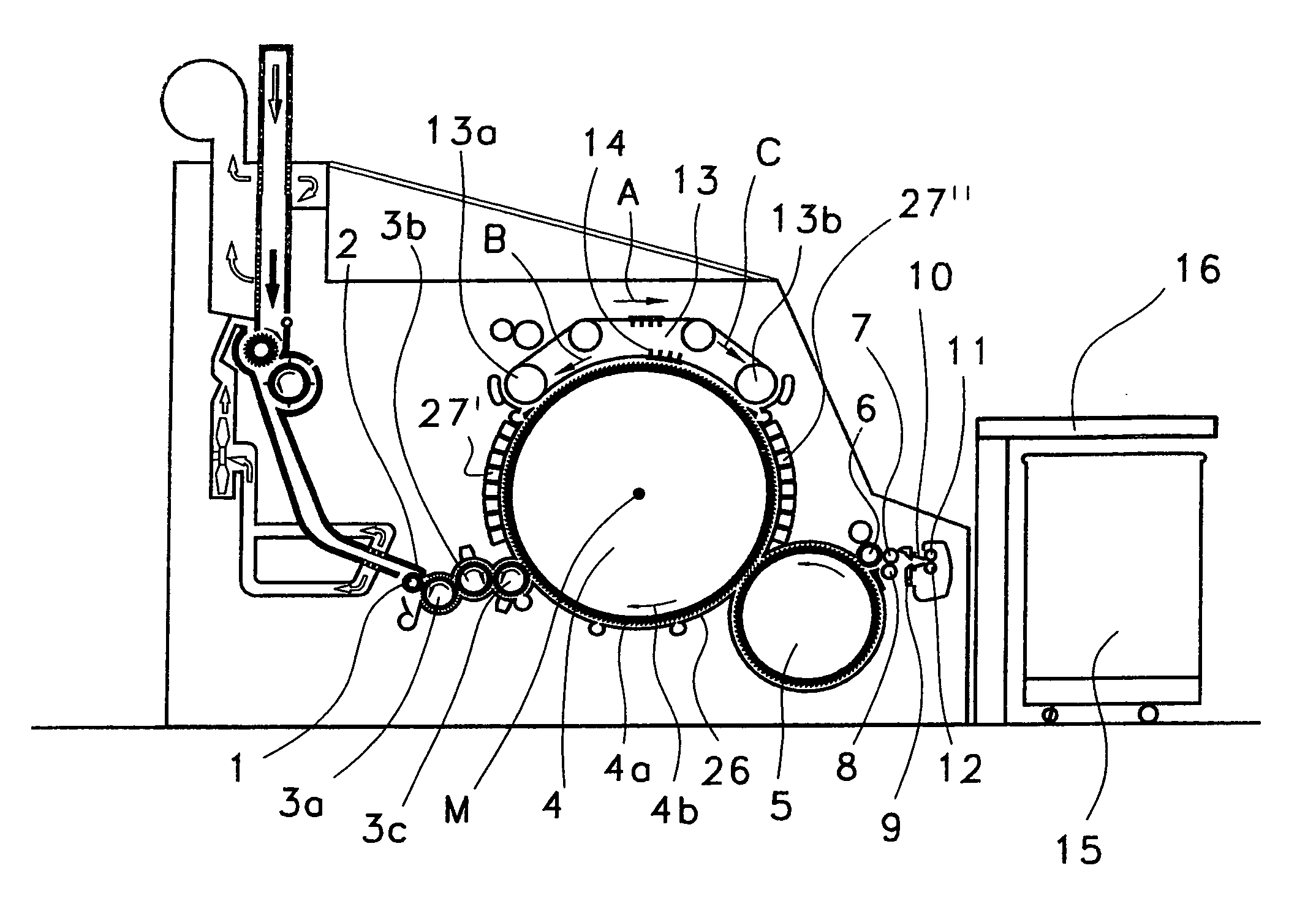
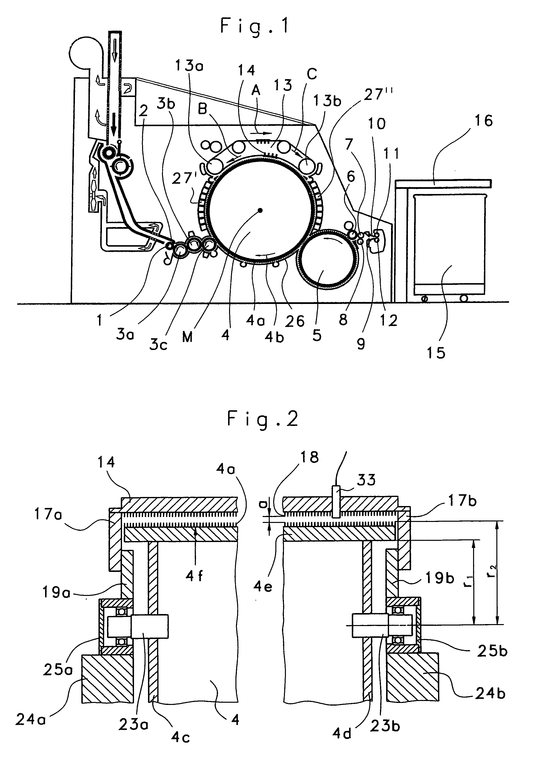
[0022]FIG. 1 shows a flat card, for example a TC 03 (Trademark) flat card made by Trützschler GmbH & Co. KG of Mönchengladbach, Germany, having a feed roller 1, feed table 2, lickers-in 3a, 3b, 3c, cylinder 4, doffer 5, stripper roller 6, nip rollers 7, 8, web-guiding element 9, web funnel 10, delivery rollers 11, 12, revolving card top 13 having card top guide rollers 13a, 13b and flats 14, can 15 and can coiler 16. The directions of rotation of the rollers are indicated by curved arrows. Reference letter M denotes the centre (axis) of the cylinder 4. Reference numeral 4a denotes the clothing and reference numeral 4b the direction of rotation of the cylinder 4. Reference letter B denotes the direction of rotation of the revolving card top 13 in the carding position and reference letter C denotes the return transport direction of the flats 14; reference numerals 27′, 27″ denote fixed carding elements and reference numeral 26 denotes a cover underneath the cylinder 4. The arrow A ind...


PUM


Abstract

In an apparatus at a spinning preparation machine, especially a flat card, roller card or the like, for the purpose of monitoring, a clothed, rapidly rotating roller lies opposite to at least one clothed and/or non-clothed component, and the spacing a between the components lying opposite to one another is changeable. To avoid contact between the components lying opposite to one another in a simple manner, in order to monitor the spacing, there is located opposite to the clothing of the roller, spaced therefrom, a sensor that is arranged to respond in the event of contact between clothing and sensor.

Description

CROSS REFERENCE TO RELATED APPLICATION [0001] This application claims priority from German Patent Application No. 10 2005 050 904.5 dated Oct. 21, 2005, the entire disclosure of which is incorporated herein by reference. BACKGROUND OF THE INVENTION [0002] The invention relates to an apparatus at a spinning preparation machine, especially at a flat card, roller card or the like, in which a clothed, rapidly rotating roller lies opposite to at least one clothed and / or non-clothed component and the spacing between the components lying opposite to one another is changeable. [0003] In flat cards, crashes occur that are caused by incorrect settings or incorrect machine operation. The repair costs for such crashes are considerable. The result of even any slight contact between a stationary component and, for example, a carding cylinder, is destructive because, in the event of contact, the roller clothing strongly takes hold of the components because of its aggressive tooth setting and, when...

Claims


Application Information

Patent Timeline
IPC IPC(8): D01B1/06
CPCD01G15/28D01G15/08G08B21/00
Inventor BREUER, ACHIMFARBER, CHRISTOPH
Owner TRUETZSCHLER GMBH & CO KG
Why Eureka
Try Eureka