Separating device for a textile processing machine

Inactive Publication Date: 2005-05-10
TRUETZSCHLER GMBH & CO KG
View PDF20 Cites 2 Cited by
  • Summary
  • Abstract
  • Description
  • Claims
  • Application Information

AI Technical Summary

Benefits of technology

[0005]It is an aim of the invention to provide a device of the kind mentioned at the beginning which avoids or mitigates the mentioned disadvantages and which

Problems solved by technology

Removal is complicated and can result in the machine becoming blocked.
A further disadvantage is t

Method used


Image

  • Separating device for a textile processing machine
  • Separating device for a textile processing machine
  • Separating device for a textile processing machine

Examples


Embodiment Construction

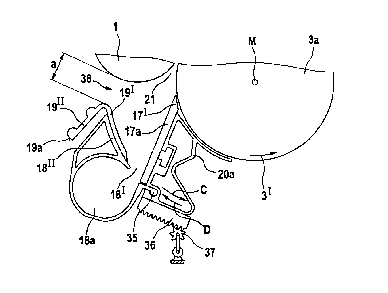
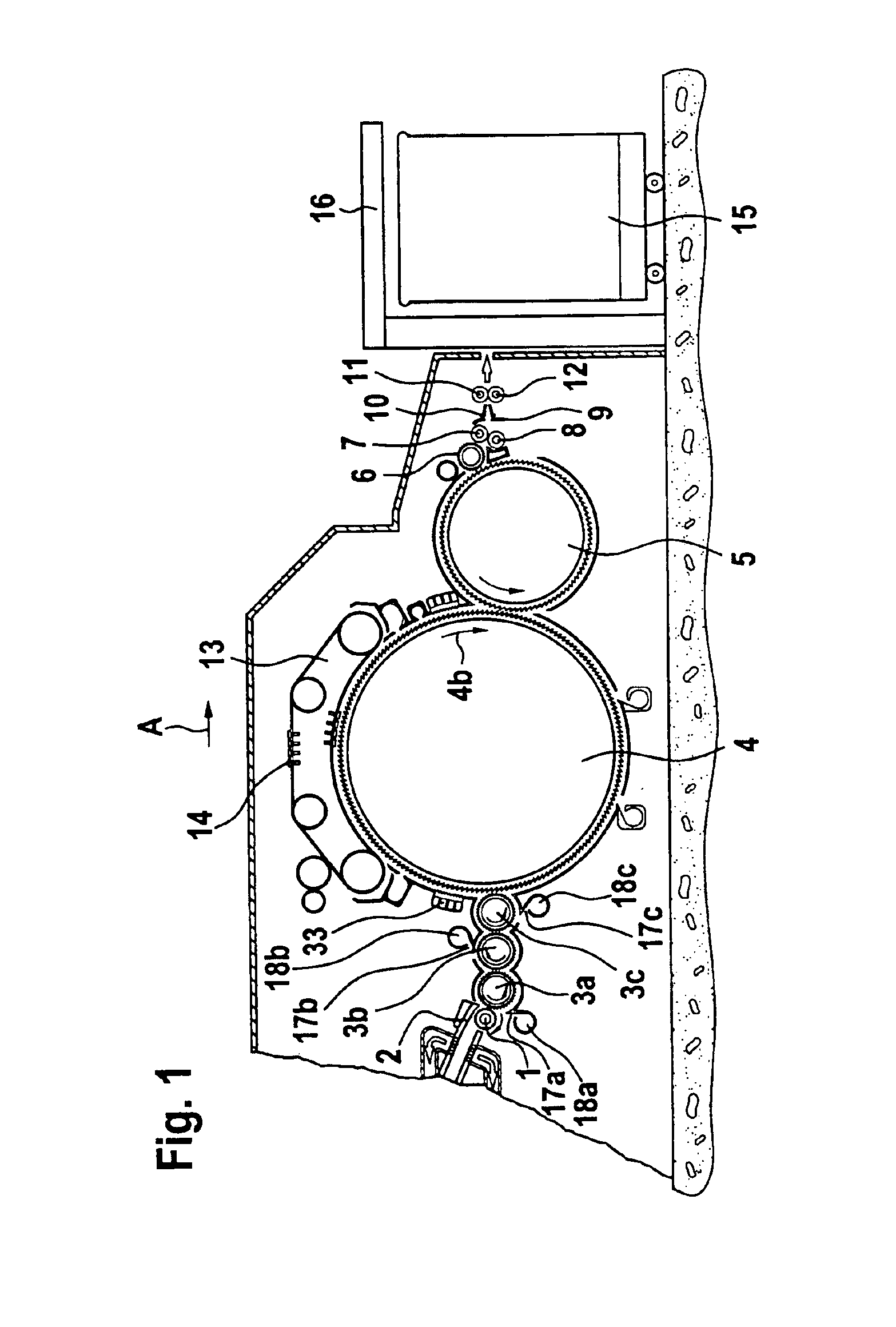
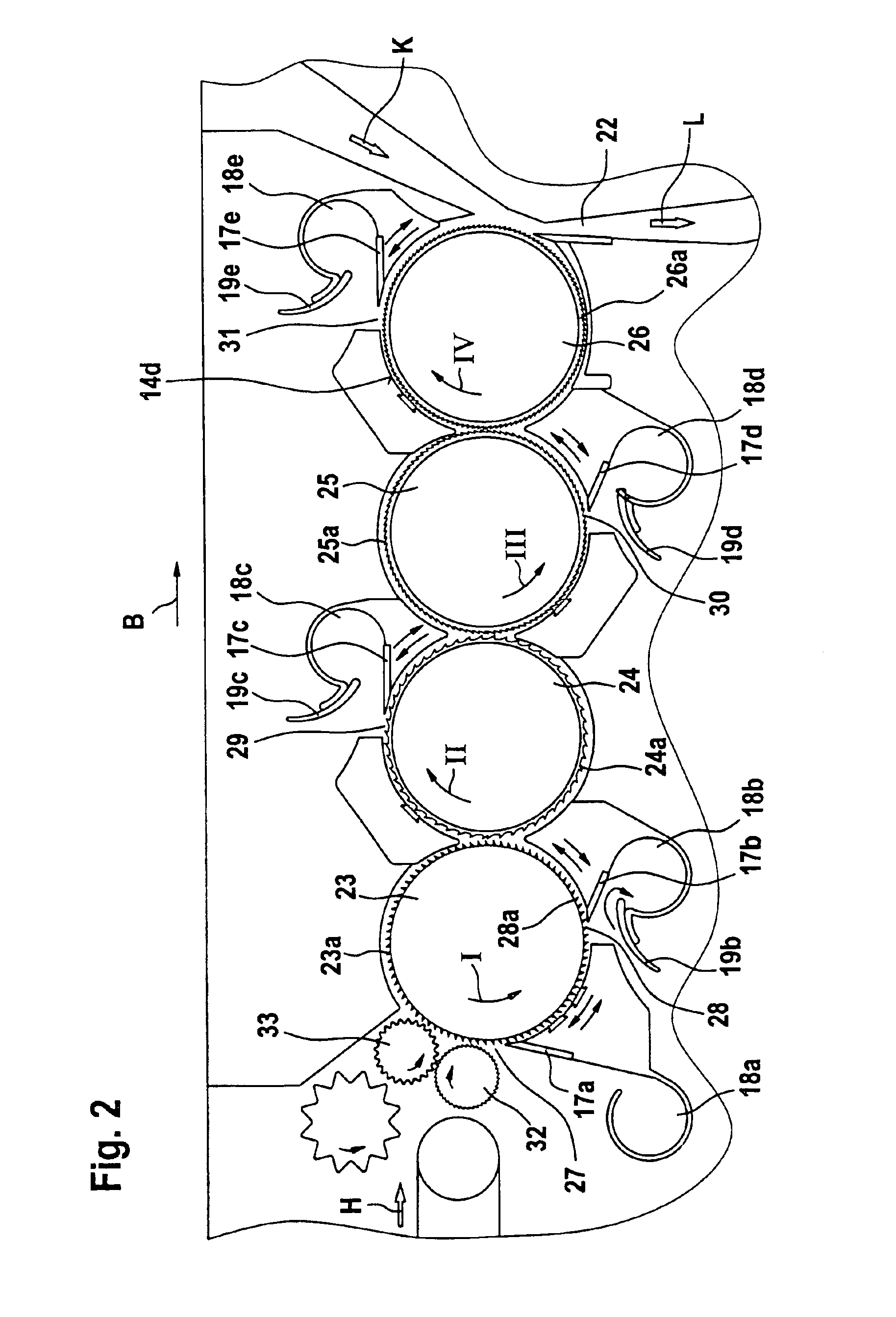
[0014]With reference to FIG. 1, a carding machine, for example a high performance carding machine DK 903 (trade mark) made by Trützschler GmbH & Co. KG, having a feed roller 1, feed table 2, lickers-in 3a, 3b, 3c, cylinder 4, doffer 5, stripper roller 6, nip rollers 7, 8, web guide element 9, sliver funnel 10, delivery rollers 11, 12, revolving card top 13 with clothed card top bars 14, can 15 and coiler 16. The directions of rotation of the rollers are indicated by curved arrows. Reference letter A denotes the operating direction. The lickers-in 3a, 3b and 3c are each associated with a separating blade 17a, 17b and 17c, respectively, having extraction hoods 18a, 18b, 18c. In the region of the extraction chambers 18a, 18b, 18c there are arranged as described below with reference to FIGS. 3a, 3b, guide elements 19a, 19b and 19c, respectively. The separating blades 17a, 17b and 17c and the extraction hoods 18a, 18b and 18c are each arranged on a respective displaceable support 20a, 20...


PUM


Abstract

In a device on a spinning preparatory machines, especially a carding machine, cleaning machine or the like for cotton having at least one separating blade for impurities, which is associated with a clothed roller, for example a licker-in or the like, wherein the separating blade is arranged on a support which is displaceable parallel to (concentrically with) the periphery of the roller, the distance between the separating blade and a fixed-position counter-element bordering the separation opening is variable.
In the event of a change in the position of the separating blade, in order to provide uniform removal of impurities and uniform supply of air into an extraction chamber, the separating blade is associated with an extraction chamber which is mounted on the support, and the extraction chamber cooperates with a fixed-position guide element which is able to guide the separated impurities and/or air into the opening of the extraction chamber.

Description

CROSS REFERENCE TO RELATED APPLICATION[0001]This application claims priority from German Patent Application No. 102 31 829.8, which is incorporated herein by reference.BACKGROUND OF THE INVENTION[0002]The invention relates to a device on a spinning preparatory machine, especially a carding machine, cleaning machine or the like for cotton having at least one separating blade for impurities, which is associated with a clothed roller, for example a licker-in or the like.[0003]In a known arrangement the separating blade is arranged on a support which is displaceable parallel to (concentrically with) the periphery of the roller and wherein the distance between the separating blade and a fixed-position counter-element bordering the separation opening is variable.[0004]In the known device of European Patent Specification No. 0 618 318, the impurities separated by the separating blade fall downwards into the space below the roller and have to be removed from there. Removal is complicated an...

Claims


Application Information

Patent Timeline
IPC IPC(8): D01G15/00D01G15/34
CPCD01G15/34
Inventor SCHMITZ, MARKUS
Owner TRUETZSCHLER GMBH & CO KG
Why Eureka
Try Eureka