Combustor for gas turbine engine

Inactive Publication Date: 2007-04-26
KAWASAKI HEAVY IND LTD
View PDF15 Cites 45 Cited by
  • Summary
  • Abstract
  • Description
  • Claims
  • Application Information

AI Technical Summary

Benefits of technology

[0016] The combustor according to the present invention for a gas turbine engine achieves desired stable, low-pollution combustion und

Problems solved by technology

Therefore, private power generation equipment does not operate always in a maximum-load operating mode and are often required to operate in a partial-load operating mode.
Although the second method can reduce the rate of NO

Method used


Image

  • Combustor for gas turbine engine
  • Combustor for gas turbine engine
  • Combustor for gas turbine engine

Examples


Embodiment Construction

[0020] A combustor in a preferred embodiment according to the present invention will be described by way of example with reference to FIGS. 1 and 2.

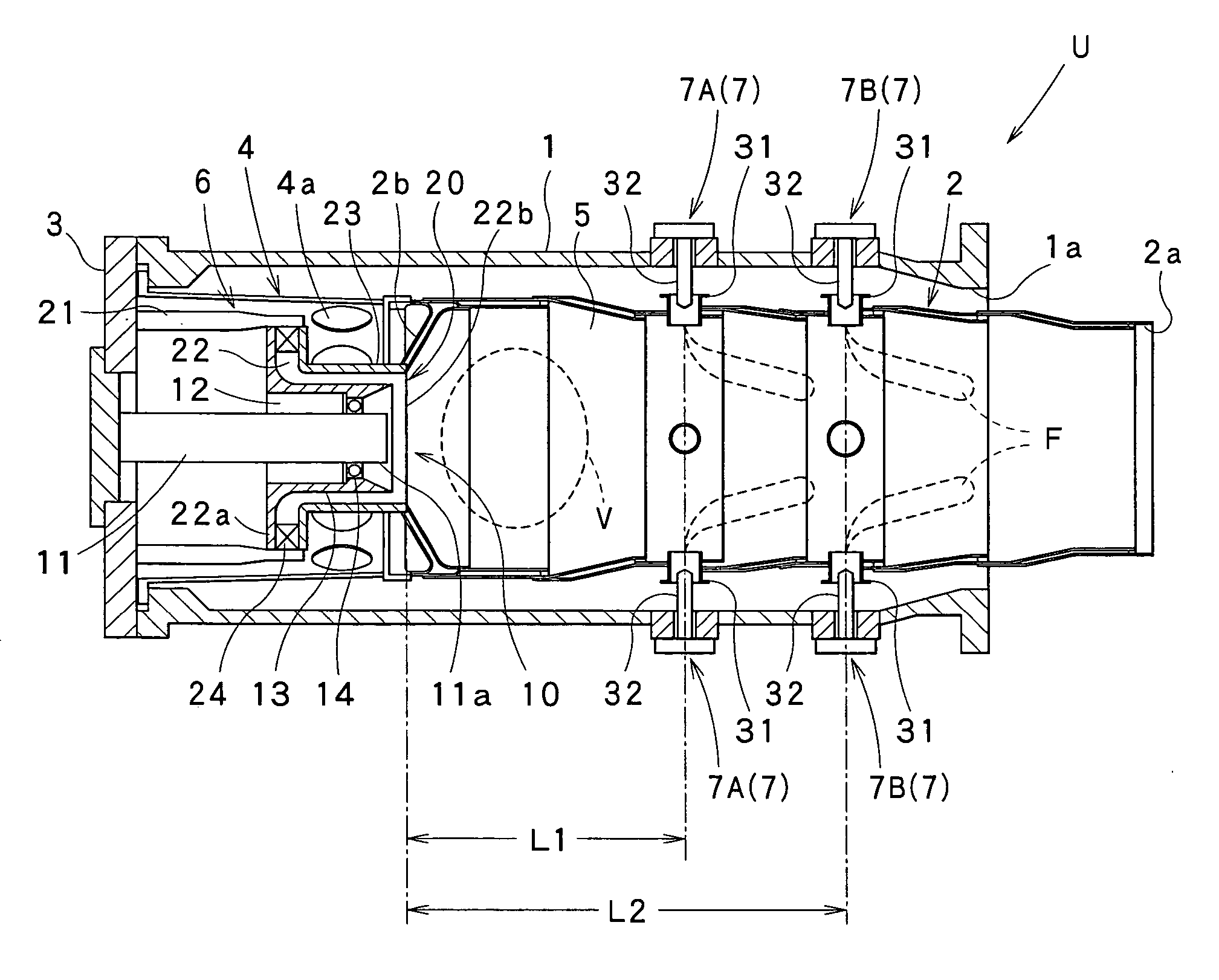
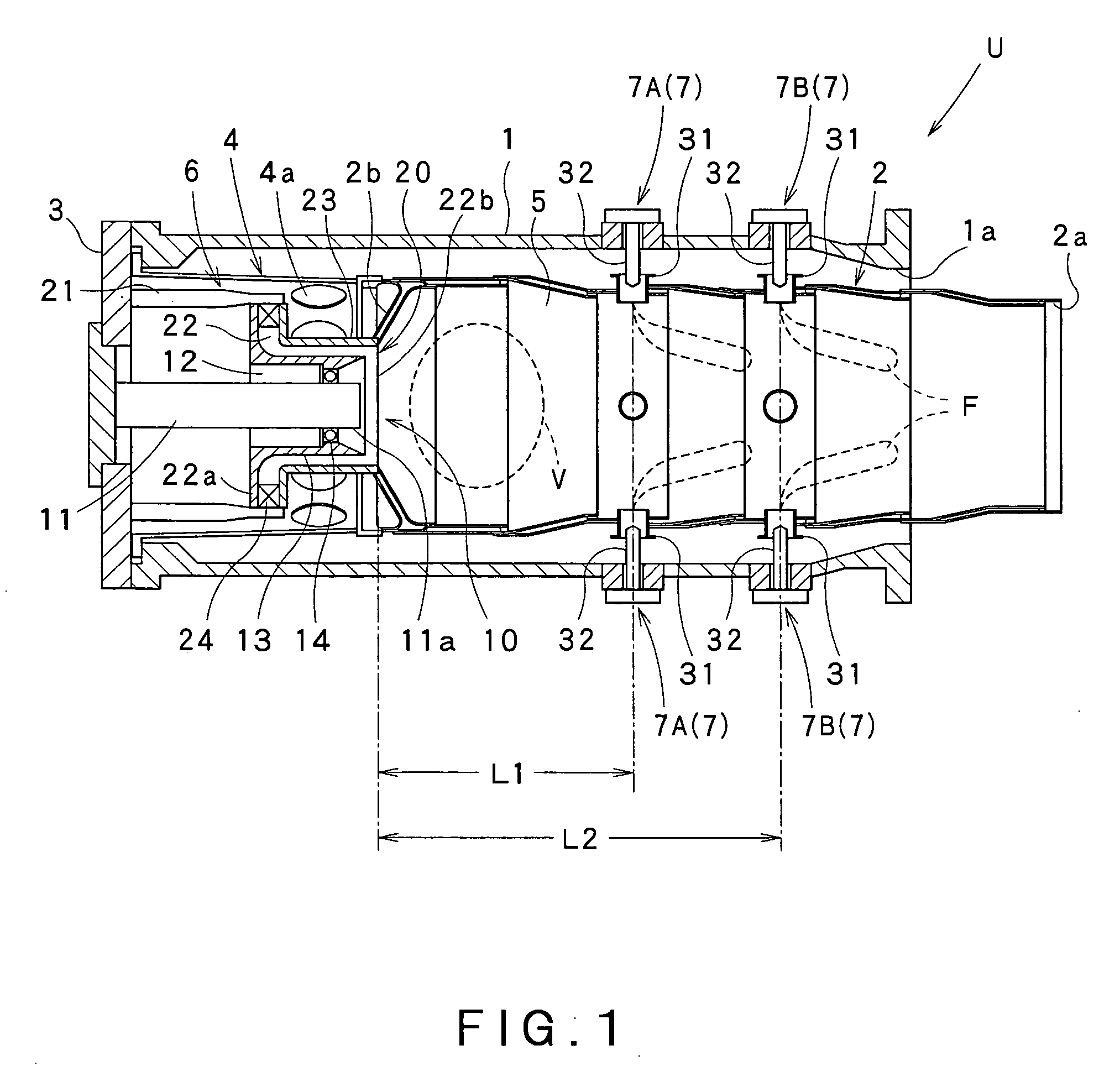
[0021] Referring to FIG. 1 showing a combustor U in a preferred embodiment according to the present invention included in a gas turbine engine, the combustor U has a combustor casing including a flow sleeve 1, namely, an outer sleeve, and an inner tube 2, namely, an inner sleeve, extended inside the flow sleeve 1.

[0022] One end of the flow sleeve 1 and one end of the inner tube 2 are closed by an end wall 3. The other end of the flow sleeve 1 is an air inlet 1a and the other end of the inner tube 2 is an exhaust outlet 2a.

[0023] The interior of the inner tube 2 is divided into a liner head 4 on the side of the end wall 3 and a combustion chamber 5 on the side of the exhaust outlet 2a by a partition wall 2b having a shape resembling an annular plate disposed at a predetermined longitudinal position.

[0024] The liner head 4 is provided ...


PUM


Abstract

A combustor for a gas turbine engine of a lean premixed combustion type, includes: a fuel jetting device configured to jet a premixed fuel into a combustion chamber so that the premixed fuel burns in a premixed combustion zone which is formed in the combustion chamber; and an additive fuel supply unit disposed downstream of the premixed combustion zone so as to additionally supply fuel into the combustion chamber. The additive fuel supply unit includes first and second additive fuel supply devices disposed in a two-stage arrangement such that the second additive fuel supply device is positioned downstream of the first additive fuel supply device.

Description

CROSS REFERENCE TO RELATED APPLICATIONS [0001] This application is based upon the prior Japanese Patent Application No. 2005-308380 filed on Oct. 24, 2005, the entire contents of which are incorporated herein by reference. BACKGROUND OF THE INVENTION [0002] 1. Field of the Invention [0003] The present invention relates to a combustor for a gas turbine engine. More specifically, the present invention relates to a combustor for a gas turbine engine, capable of making the combustor of the gas turbine engine achieve desired stable, low-pollution combustion under partial load. [0004] 2. Description of the Related Art [0005] Private power generation equipment has progressively come into wide use recently, and gas turbine engines are used widely as power units for private power generation equipment. Different time zones have different power demands, respectively, on private power generation equipment. Therefore, private power generation equipment does not operate always in a maximum-load o...

Claims


Application Information

Patent Timeline
IPC IPC(8): F23R3/30
CPCF23R3/06F23R3/14F23R3/346
Inventor MATSUMOTO, KIYOSHIOKUTO, ATSUSHIKINOSHITA, YASUHIRO
Owner KAWASAKI HEAVY IND LTD
Why Eureka
Try Eureka