Control device of elevator
a control device and elevator technology, applied in the direction of elevators, building lifts, transportation and packaging, etc., can solve the problems of difficult to identify the cause of the actuation, difficult to determine, and the output of the actuation signal may be erroneously output, so as to achieve efficient determination
- Summary
- Abstract
- Description
- Claims
- Application Information
AI Technical Summary
Benefits of technology
Problems solved by technology
Method used
Image

Examples
embodiment 1
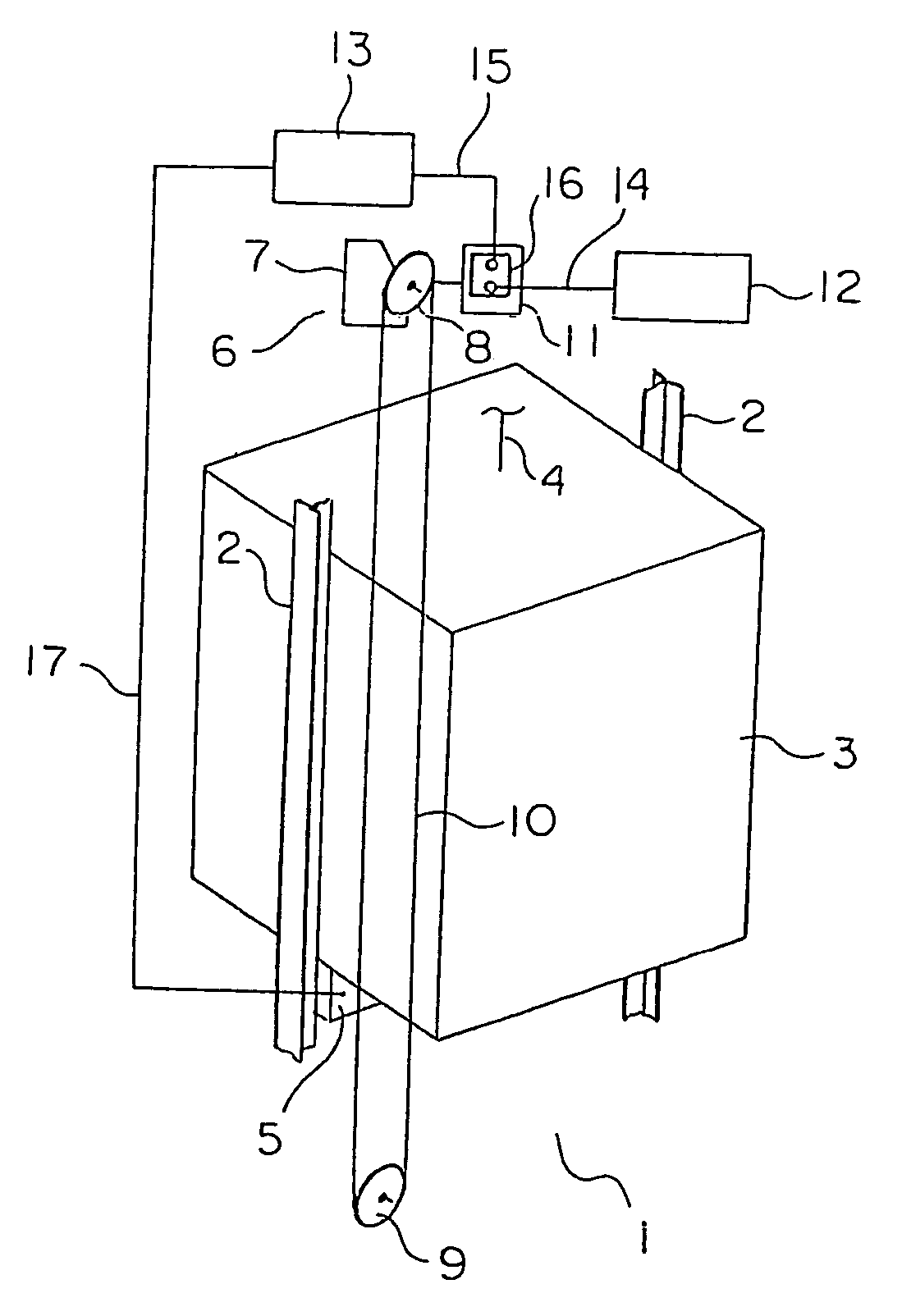
[0043]FIG. 1 is a schematic diagram showing an elevator apparatus, according to Embodiment 1 of the present invention. Referring to FIG. 1, a pair of car guide rails 2 are arranged within a hoistway 1. A car 3 is guided by the car guide rails 2 as it is raised and lowered in the hoistway 1. Arranged at the upper end portion of the hoistway 1 is a hoisting machine (not shown) for raising and lowering the car 3 and a counterweight (not shown). A main rope 4 is wound around a drive sheave of the hoisting machine. The car 3 and the counterweight are suspended in the hoistway 1 by means of the main rope 4. Mounted to the car 3 are a pair of safety devices 5 opposed to the respective guide rails 2 and serving as braking means. The safety devices 5 are arranged on the underside of the car 3. Braking is applied to the car 3 upon actuating the safety devices 5.
[0044] Also arranged at the upper end portion of the hoistway 1 is a governor 6 serving as a car speed detecting means for detecting...
embodiment 2
[0056]FIG. 4 is a schematic diagram showing an elevator apparatus according to Embodiment 2 of the present invention. Referring to FIG. 4, the car 3 has a car main body 27 provided with a car entrance 26, and a car door 28 that opens and closes the car entrance 26. Provided in the hoistway 1 is a car speed sensor 31 serving as car speed detecting means for detecting the speed of the car 3. Mounted inside the control panel 13 is an output portion 32 electrically connected to the car speed sensor 31. The battery 12 is connected to the output portion 32 through the power supply cable 14. Electric power used for detecting the speed of the car 3 is supplied from the output portion 32 to the car speed sensor 31. The output portion 32 is input with a speed detection signal from the car speed sensor 31.
[0057] Mounted on the underside of the car 3 are a pair of safety devices 33 serving as braking means for braking the car 3. The output portion 32 and each safety device 33 are electrically ...
embodiment 3
[0074]FIG. 8 is a schematic diagram showing an elevator apparatus according to Embodiment 3 of the present invention. Referring to FIG. 8, provided at the car entrance 26 is a door closed sensor 58, which serves as a door closed detecting means for detecting the open or closed state of the car door 28. An output portion 59 mounted on the control panel 13 is connected to the door closed sensor 58 through a control cable. Further, the car speed sensor 31 is electrically connected to the output portion 59. A speed detection signal from the car speed sensor 31 and an open / closed detection signal from the door closed sensor 58 are input to the output portion 59. On the basis of the speed detection signal and the open / closed detection signal thus input, the output portion 59 can determine the speed of the car 3 and the open or closed state of the car entrance 26.
[0075] The output portion 59 is connected to each safety device 33 through the emergency stop wiring 17. On the basis of the sp...
PUM
 Abstract
Description
Claims
Application Information
 - Generate Ideas
- Intellectual Property
- Life Sciences
- Materials
- Tech Scout
- Unparalleled Data Quality
- Higher Quality Content
- 60% Fewer Hallucinations
Browse by: Latest US Patents, China's latest patents, Technical Efficacy Thesaurus, Application Domain, Technology Topic, Popular Technical Reports.
© 2025 PatSnap. All rights reserved.Legal|Privacy policy|Modern Slavery Act Transparency Statement|Sitemap|About US| Contact US: help@patsnap.com