Three-dimensional shape measuring apparatus, program, computer-readable recording medium, and three-dimensional shape measuring method

a three-dimensional shape and measuring apparatus technology, applied in the field of three-dimensional shape measuring apparatus, can solve problems such as the extension of the imaging tim

Active Publication Date: 2007-04-26
ORMON CORP
View PDF1 Cites 42 Cited by
  • Summary
  • Abstract
  • Description
  • Claims
  • Application Information

AI Technical Summary

Benefits of technology

[0008] According to several aspects of the invention provide there is provided a three-dimensional shape measuring apparatus which measures the three-dimensional shape of a target object by analyzing an optical pattern projected onto the target object and the brightness of the optical pattern being periodically changed according to a position; the three-dimensional shape measuring apparatus includes a line sensor which reads the optical pattern, projected onto the target object, as an image; and an image analysis unit which computes and / or analyzes the phase of the optical pattern in a pixel included in the image read by the line sensor based on brightness values of the pixel and one or more neighboring pixel(s) in the image, the image analysis unit computing height information on the target object based on the computed phase.

Problems solved by technology

However, when the area camera is used, because the target object does not fit into one imaging visual field, it is necessary that the area camera be moved in both the lengthwise direction and the crosswise direction to take the one imaging visual field while the one imaging visual field is divided into plural portions, which results in the problem that the imaging time is lengthened.

Method used


Image

  • Three-dimensional shape measuring apparatus, program, computer-readable recording medium, and three-dimensional shape measuring method
  • Three-dimensional shape measuring apparatus, program, computer-readable recording medium, and three-dimensional shape measuring method
  • Three-dimensional shape measuring apparatus, program, computer-readable recording medium, and three-dimensional shape measuring method

Examples


Embodiment Construction

[0029] In the conventional techniques, there is difficulty in arranging the line sensor or there is a problem that it takes a long time to take the image.

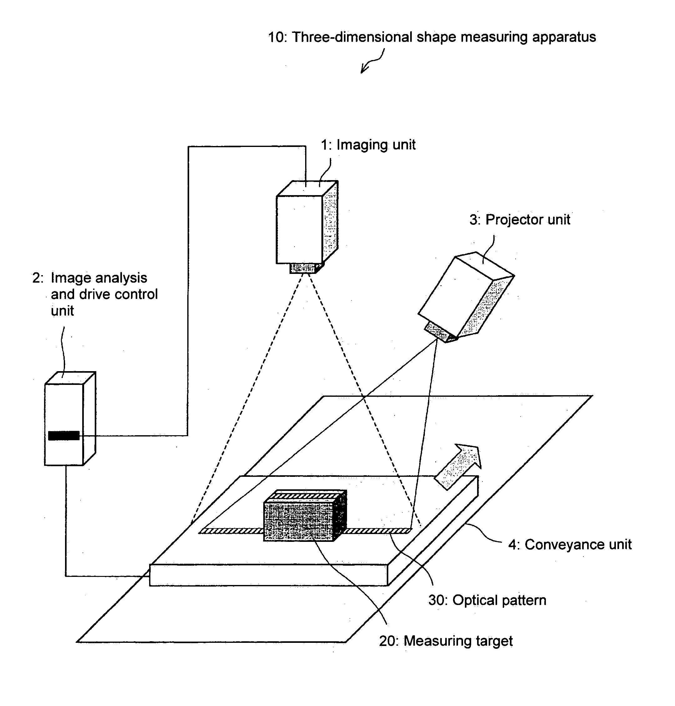
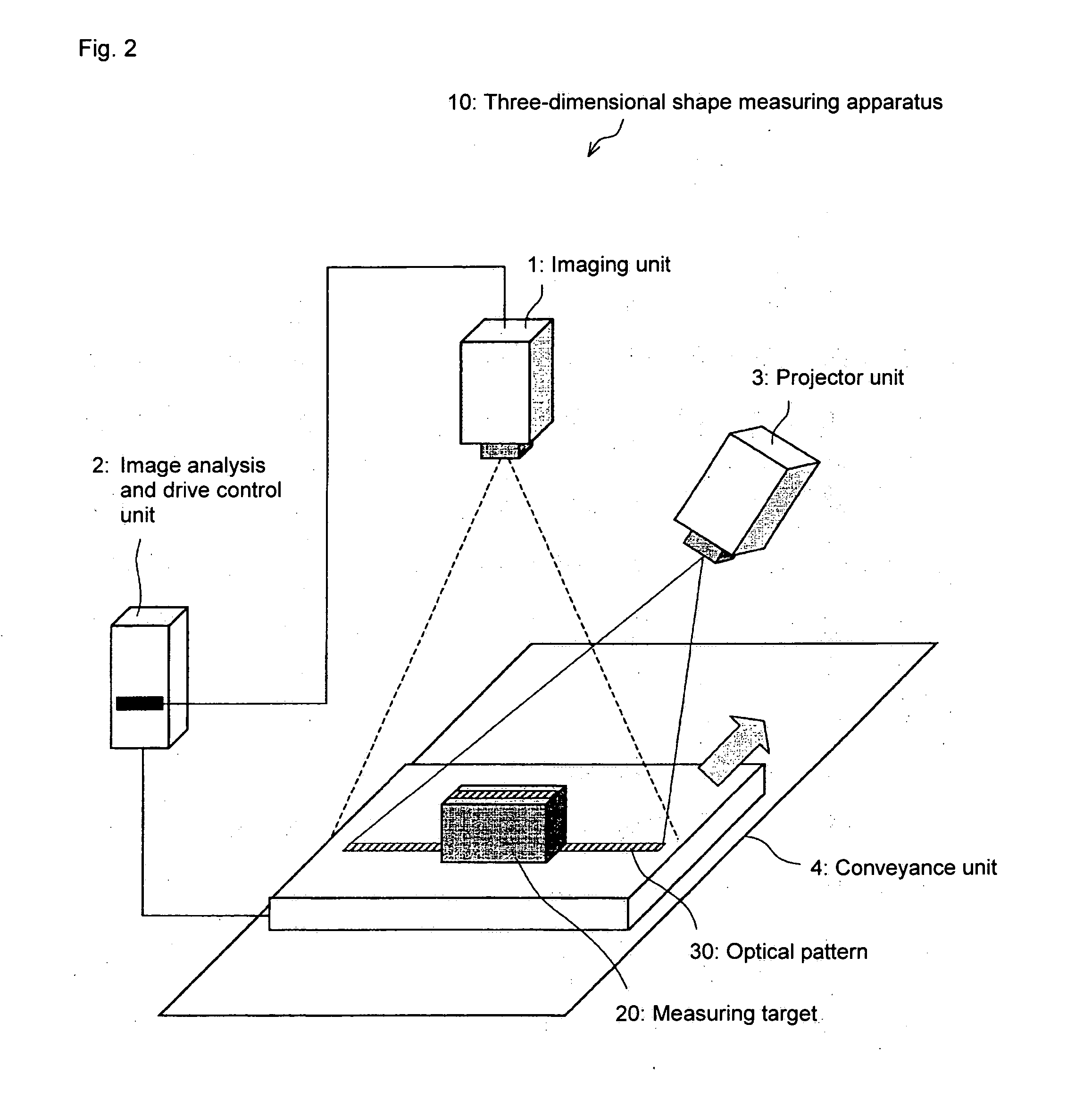
[0030] For example, the temporal fringe analysis method of taking the image of the same portion of the target object plural times from the same angle while changing the phase of the optical pattern projected onto the target object is used as the fringe analysis method in the technique described in Japanese Patent Laid-Open No. 2002-286433. In this case, it is necessary that all the line sensors be strictly arranged in parallel in order to taken the image of the same portion of the target object conveyed in a linear direction. It is also necessary that all the line sensors be arranged at the same distance from a reference plane on which the target object is placed. Additionally, it is necessary that all the line sensors be arranged in the same attitude in order to taken the image from the same angle. For example, four line sensors ...


PUM


Abstract

A three-dimensional shape measuring apparatus of the invention is an apparatus which measures a three-dimensional shape of a target object by analyzing an optical pattern projected to the target object. The three-dimensional shape measuring apparatus includes a line sensor and an image analysis unit. The line sensor reads the target object, onto which the optical pattern is projected, as the image. The image analysis unit analyzes the optical pattern in the image read by the line sensor based on a spatial fringe analysis method, and the image analysis unit computes the three-dimensional shape information on the target object. An apparatus, method and program for measuring the three-dimensional shape of an object by analyzing an optical pattern projected onto the object. The phase of a pixel included in an image taken of the optical pattern is determined based on the brightness values of the pixel and at least one neighboring pixel in the image; thus the height information of the object can be determined. In addition, the height of the target object at a given position can be computed based on how much the phase of the optical pattern projected onto a certain position of the object is shifted from a reference phase.

Description

BACKGROUND OF THE RELATED ART [0001] 1. Field of the Invention [0002] The present invention relates to a three-dimensional shape measuring apparatus which measures a three-dimensional shape of a target object. [0003] 2. Description of the Related Art [0004] An example of means for obtaining three-dimensional shape information on an object by image analysis includes a method of analyzing a deformation amount of the optical pattern changed according to the three-dimensional shape of the target object by projecting an optical pattern onto a target object existing in a predetermined imaging visual field. A light-section method, a spatial encoding method, a fringe analysis method can be cited as a typical example. These methods are based on the principle of triangulation. Among others, for the fringe analysis method, there are proposed many techniques such as spatial fringe analysis and temporal fringe analysis, and the fringe analysis method is known as a technique in which high measure...

Claims


Application Information

Patent Timeline
Patent Type & Authority Applications(United States)
IPC IPC(8): G06K7/10
CPCG01B11/2522G06T7/0057G06T7/521
Inventor SUWA, MASAKIITO, YOSHIROMITSUMOTO, DAISUKEYOSHINO, MASANAOKOITABASHI, HIROYOSHIASOKAWA, YOSHINOBU
Owner ORMON CORP
Why Eureka
Try Eureka