

Image pickup apparatus and method of manufacturing the same
- Summary
- Abstract
- Description
- Claims
- Application Information
AI Technical Summary
Benefits of technology
Problems solved by technology
Method used
Image

Examples
example 1
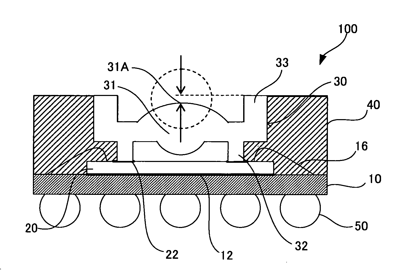
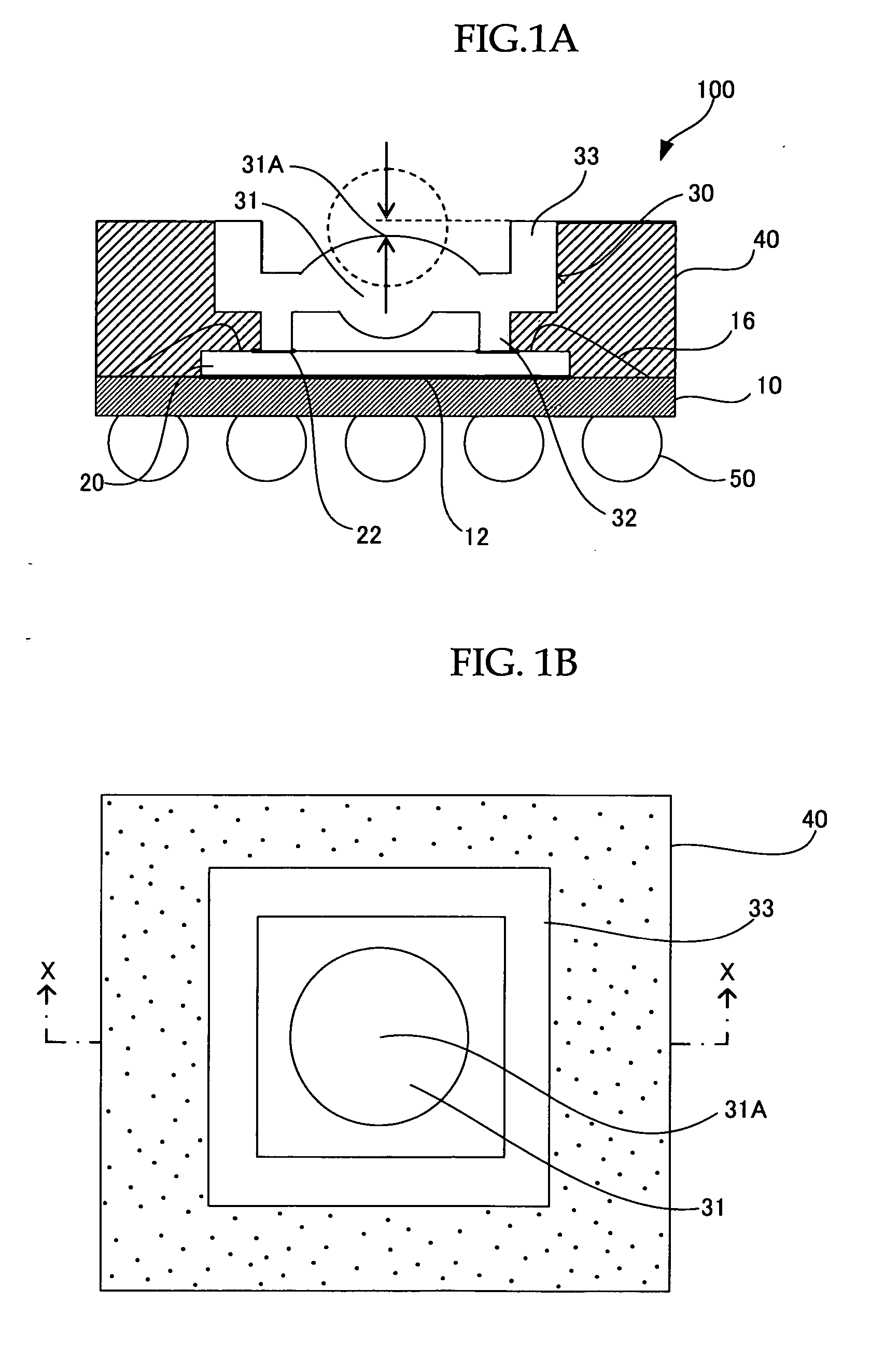
[0058] An image pickup apparatus 100 according to the first Example of the present invention is shown in FIGS. 1A and 1B. FIG. 1A is a cross-sectional view taken along X-X line in FIG. 1B.
[0059] In these drawings an image pickup device 20 is mounted on one main surface (upper surface) of a support board 10, and is fixed to it with a die bonding material 12. The electrode of the image pickup device 20 and the electrode of the support board 10 are connected together with wires 16.
[0060] A lens component 30 made of synthetic quartz glass is mounted on the image pickup device 20, and is fixed to it with an adhesive 22.
[0061] The circumferential surface of the lens component 30, the exposed surface of the image pickup device 20, and the surface of the support board 10 around the image pickup device 20 are all sealed with sealing resin 40, encapsulating the wires 16.
[0062] Meanwhile, a plurality of external connection terminals 50 is provided on the other main surface (lower surface) ...
example 2
[0102] The second Example of the image pickup apparatus of the present invention is shown in FIGS. 8A and 8B.
[0103] These drawings show a cross-sectional view of an image pickup apparatus taken along X-X line, as does FIG. 1A.
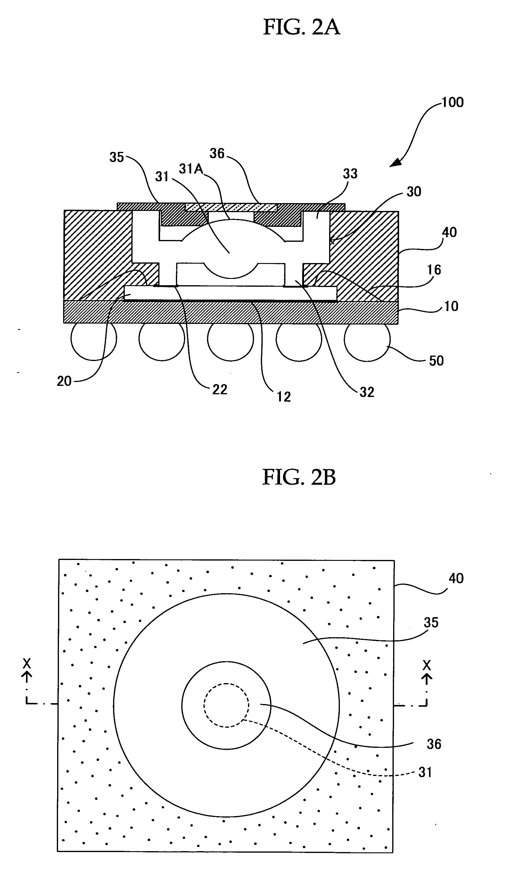
[0104] As shown in FIG. 8A, an image pickup apparatus 200 is provided with a step part 33a inside the protrusion part 33 of the lens component 30, and the infrared ray (IR) filter 36 is attached to and retained by the step part 33a.
[0105] Moreover, an image pickup apparatus 210 shown in FIG. 8B is provided with a two-stage step part 33b, whereby the infrared ray (IR) filter 36 and light shielding plate for diaphragm 35 overlap one another in the optical axis direction, so that they are retained in the step part 33b.
[0106] The step part 33b includes a step part located on the image pickup 20 side, and a step part having a larger opening than that step part. The light shielding plate for diaphragm 35 and infrared ray (IR) filter 36 are attached to and retaine...
example 3
[0108] The third Example of the image pickup apparatus of the present invention is shown in FIGS. 9A and 9B.
[0109] These drawings show a cross-sectional view of an image pickup apparatus taken along X-X line, as does FIG. 1A.
[0110] In both an image pickup apparatus 300 shown in FIG. 9A and an image pickup apparatus 310 shown in FIG. 9B, the infrared ray (IR) filter 36 is provided in a space (gap) created between the image pickup device 20 and the lens part 31 of the lens component 30. To be more specific, the infrared ray (IR) filter 36 is positioned closer to the image pickup device 20 compared to Examples described above.
[0111] As in the case of Example 1, the light shielding plate for diaphragm 35 is received and retained by the protrusion part 33 in the image pickup apparatus 310.
[0112] The plan view of the infrared ray (IR) filter 36, viewed from the image pickup device 20, of the image pickup apparatuses 300 and 310 is shown in FIG. 9C. This drawing corresponds to the port...
PUM
 Abstract
Description
Claims
Application Information