[0007] What is needed is therefore a
communications system as initially referred to in which signalling can be reduced. Still further a
communications system is needed through which unnecessary changes of the attachment of a mobile
station to core nodes can be avoided in general. Moreover a system is needed through which
pooling of core nodes can be taken
advantage of to a better extent than hitherto, particularly
pooling of CS core nodes. Still further a system is needed through which the disadvantages referred to above when
pooling is used in combination with the feature combined procedures or network
operation mode 1 can be overcome. Further yet a system is needed through which maintenance of pooled CS core nodes, particularly MSCs, is facilitated when the Gs interface is active, or when combined procedures or Network
Operation Mode I is implemented. Still further a system is needed through which changes of core nodes can be avoided when for example a CS core node in a pool crashes, or when a new CS core node, particularly an MSC, is introduced in a network or when an MSC is down for maintenance reasons etc. Still further a system is needed through which the rigidity and inflexibility of using MSC algorithms for selection of an MSC via an SGSN can be avoided and through which a coordinated change of IMSI based MSCs selections can be avoided when an MSC for some reason has been changed for one, or particularly a plurality, of mobile stations. Still further a system is needed through which, even if a mobile
station moves and changes SGSN attachment from one SGSN to another, it is not necessary to change MSC. Still further a system is needed through which, when there is a change in SGSN for a mobile
station already having changed MSC, the SGSN shall have the option to be aware of which is the current MSC. Still further a PS core node is needed through which one or more of the above mentioned objects can be achieved. Moreover a CS core node as initially referred to is needed through the implementation of which one or more of the above mentioned objects can be achieved, as well as a home location node which can assist in achieving one or more of the above mentioned objects. Further yet a method is needed through which one or more of the above mentioned objects can be achieved.
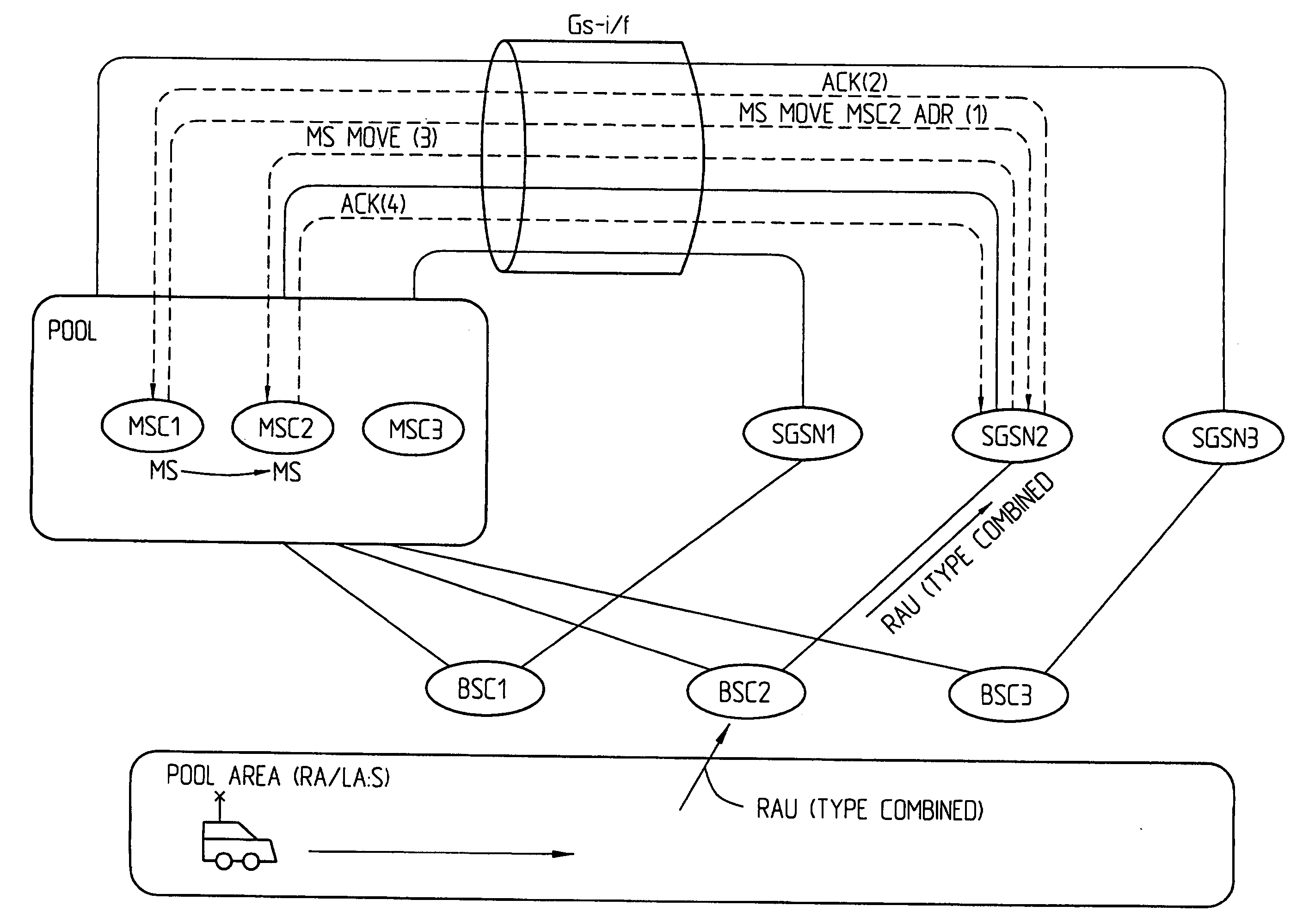
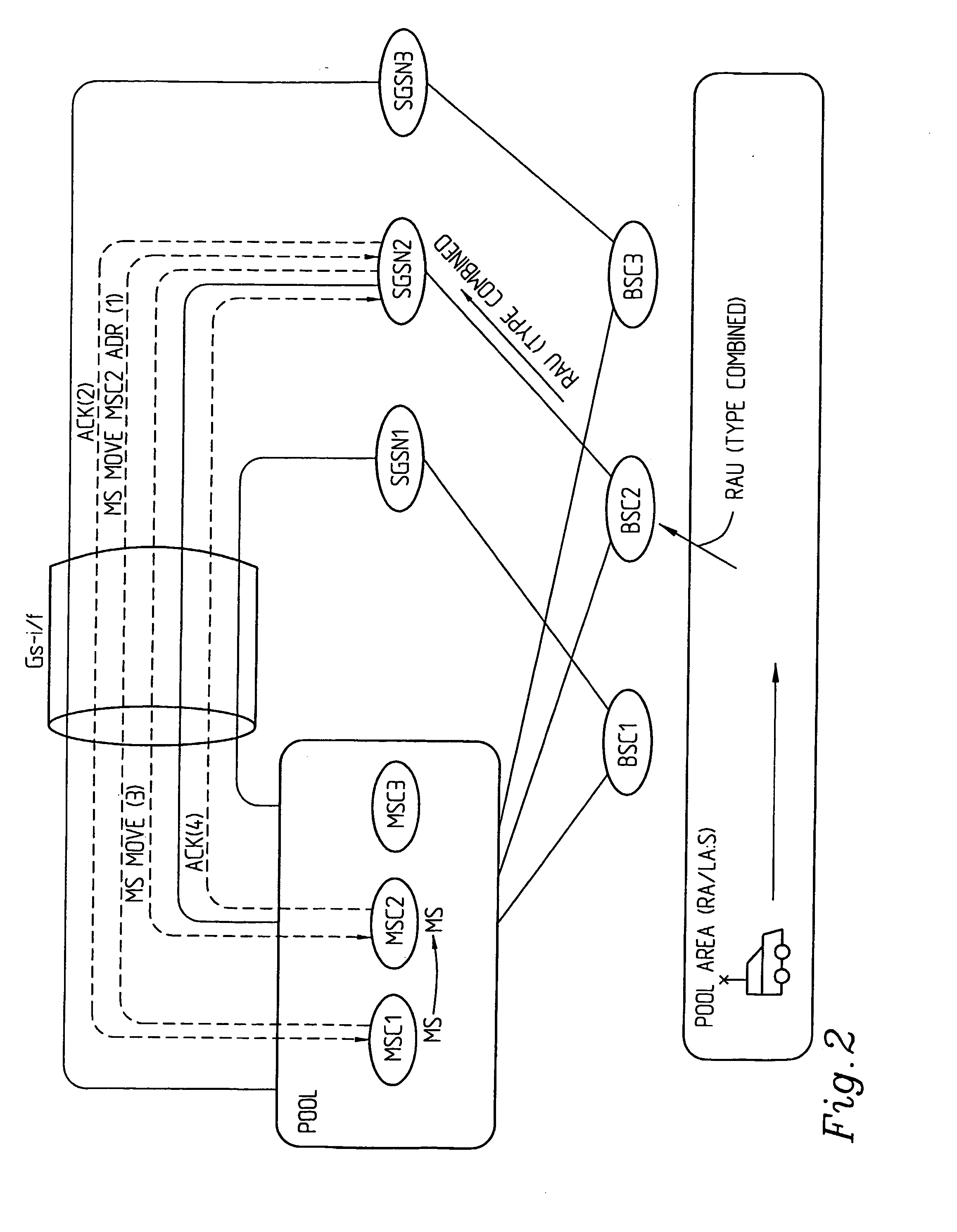
[0015] The invention also provides for a PS core node used in a communication system supporting communication of data and comprising a number of PS core nodes and further comprising a pool of CS core nodes and wherein an interface (Gs) is used for communication between PS core nodes and CS core nodes. The PS core node comprises means for receiving and responding to an information message from a CS core node when one or more MSs have changed / or are changing CS core nodes and contains the address of the CS core node to which the MS or the MSs are changing / have changed. Particularly said information message is sent / responded to over the Gs interface and comprises information about when the PS core node should perform a Location Update relating to the MS(s) towards the other / new PS core node. The PS core node particularly comprises an SGSN / CGSN receiving an information message from / responding to a CS core node comprising an MSC. The PS core node particularly comprises second information means for sending / receiving a second information message to / from another PS core node to which an MSC moves / attaches or has moved / attached or from which an MS has moved, wherein said second information message contains information about the current CS core node to which the MS is connected / attached. Said second information message even more particularly comprises an existing message extended with information relating to current CS core node, particularly MSC. The extended existing message particularly comprises an extended SGSN context response used during an Inter SGSN Routing Area Update. Particularly, after having received (taken over) an MS from another PS core node, the PS core node selects the current CS core node and sends a location update message to said current CS core node, thus avoiding a CS core node change due to a PS core node change for the mobile station in question.

