Visible light control apparatus, visible light control circuit, visible light communication apparatus, and visible light control method

a technology of visible light and control circuit, which is applied in the direction of electromagnetic transmission, electromagnetic transceivers, close-range type systems, etc., can solve the problem of not considering the brightness adjustment of the visible light at all

Inactive Publication Date: 2007-04-26
NEC CORP
View PDF2 Cites 134 Cited by
  • Summary
  • Abstract
  • Description
  • Claims
  • Application Information

AI Technical Summary

Benefits of technology

[0016] The visible light control apparatus of the present embodiments may further comprise emission time ratio relaxation control means for relaxing a rate of change over time of the changed emission time ratio at a change point and allowing the visible light to be emitted at the relaxed emission time ratio.
[0017] In the visible light control apparatus of the present embodiments, the emission time ratio control means may include: period modulated signal generation means for generating a period modulated signal that changes a period of the modulated signal which is generated by the modulation means; and driving signal generation means for combining the period modulated signal which is generated by the period modulated signal generation means and the modulated signal which is generated by the modulation means, and thereby generating a driving signal that controls the blinking of the visible light, and the emission time ratio control means may control the blinking of the visible light based on the driving signal generated by the driving signal generation means, change the predetermined emission time ratio, and allow the visible light to be emitted at the changed emission time ratio.
[0021] In the visible light control apparatus of the present embodiments, the emission time ratio relaxation control means may relax, based on the multilevel PPM signal or the inverted multilevel PPM signal which is converted by the signal conversion means, a rate of change over time of the changed emission time ratio at a change point.
[0026] The visible light control method of the present embodiments may further comprise an emission time ratio relaxation control step of relaxing a rate of change over time of the changed emission time ratio at a change point and allowing the visible light to be emitted at the relaxed emission time ratio.
[0031] In the visible light control method of the present embodiments, in the emission time ratio relaxation control step, based on the multilevel PPM signal or the inverted multilevel PPM signal which is converted in the signal conversion step, a rate of change over time of the changed emission time ratio at a change point may be relaxed.

Problems solved by technology

However, although the aforementioned patent document 1 and non-patent document 1 disclose the emission of visible light which contains information, there is no consideration at all of the adjustment of the brightness of the visible light to an arbitrary level by changing an emission time ratio, based on which the visible light is emitted.

Method used


Image

  • Visible light control apparatus, visible light control circuit, visible light communication apparatus, and visible light control method
  • Visible light control apparatus, visible light control circuit, visible light communication apparatus, and visible light control method
  • Visible light control apparatus, visible light control circuit, visible light communication apparatus, and visible light control method

Examples


first embodiment

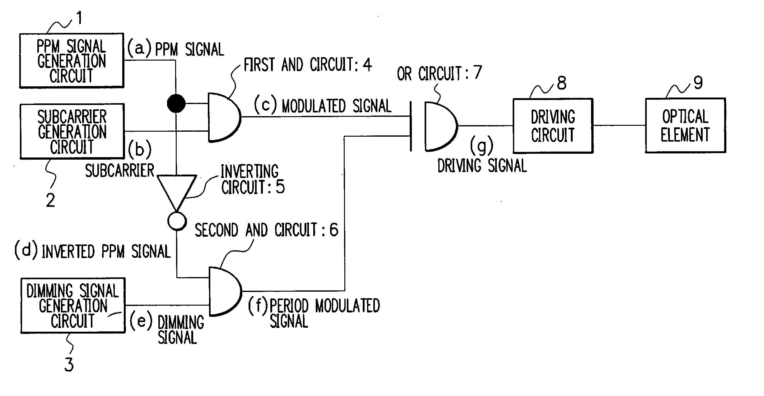
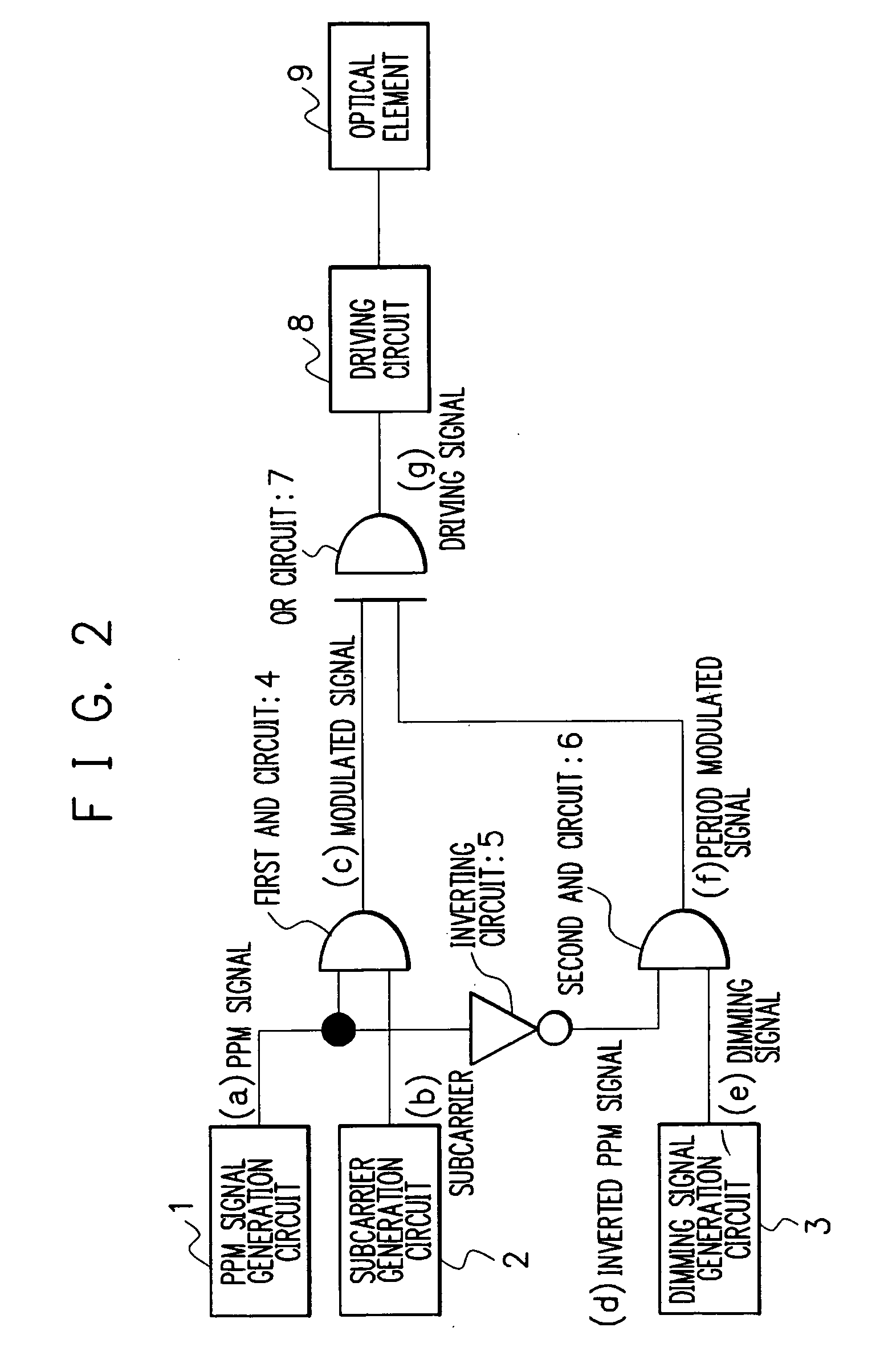
[0052] First, the configuration of a visible light control apparatus according to the present embodiment will be described with reference to FIG. 2.

[0053] The visible light control apparatus according to the present embodiment includes a PPM (Pulse Position Modulation) signal generation circuit 1, a subcarrier generation circuit 2, a dimming signal generation circuit 3, a first AND circuit 4, an inverting circuit 5, a second AND circuit 6, an OR circuit 7, a driving circuit 8, and an optical element 9.

[0054] The PPM signal generation circuit 1 is a circuit for outputting a PPM signal. The PPM signal generation circuit 1 converts a main digital signal to a PPM signal at a ratio of one PPM signal per frame which is determined by a frame signal, and then outputs the converted PPM signal.

[0055] The conversion (modulation) from the main signal to a PPM signal which is performed by the PPM signal generation circuit 1 is, for example, such that the main signal is converted to a PPM sign...

second embodiment

[0071] Now, a second embodiment will be described.

[0072] A visible light control apparatus according to the second embodiment is characterized in that the PPM signal generation circuit 1 that composes the visible light control apparatus according to the first embodiment shown in FIG. 2 and outputs a PPM signal is replaced, as shown in FIG. 6, with an inverted PPM signal generation circuit 10 that outputs an inverted PPM signal which is an inverted version of a PPM signal. By this, as in the visible light control apparatus according to the first embodiment, the emission time ratio of the optical element 9 can be changed and visible light to be emitted from the optical element 9 can be adjusted to an arbitrary brightness level. The visible light control apparatus according to the second embodiment will be described below with reference to FIGS. 6 and 7.

[0073] First, the configuration of the visible light control apparatus according to the second embodiment will be described with ref...

third embodiment

[0082] Now, a third embodiment will be described.

[0083] A visible light control apparatus according to the third embodiment is characterized in that, as shown in FIG. 8, a PPM signal / inverted PPM signal generation circuit 11 that outputs a PPM signal or an inverted PPM signal is provided. By this, a PPM signal or an inverted PPM signal is outputted from the PPM signal / inverted PPM signal generation circuit 11 and the same control operation as that of the visible light control apparatus according to the first or second embodiment can be performed. The visible light control apparatus according to the third embodiment will be described below with reference to FIGS. 8 and 9.

[0084] First, the configuration of the visible light control apparatus according to the third embodiment will be described with reference to FIG. 8.

[0085] The visible light control apparatus according to the third embodiment is configured such that the PPM signal generation circuit 1 that composes the visible ligh...


PUM


Abstract

There is provided a visible light control apparatus including: a modulation unit (corresponding to a PPM signal generation circuit, a subcarrier generation circuit, and a first AND circuit) that modulates a subcarrier and thereby generates a modulated signal; a visible light control unit (corresponding to a driving circuit) that controls blinking of visible light which contains information based on the modulated signal modulated by the modulation unit and allows the visible light to be emitted at a predetermined emission time ratio; and an emission time ratio control unit (corresponding to a dimming signal generation circuit, an inverting circuit, a second AND circuit, and an OR circuit) that changes the predetermined emission time ratio and allows the visible light to be emitted at the changed emission time ratio.

Description

BACKGROUND OF THE INVENTION [0001] 1. Field of the Invention [0002] The present invention relates to a visible light (light that the human eye can see) control apparatus and a visible light control circuit that control blinking of visible light, a visible light communication apparatus that performs information communication using visible light that is controlled by the visible light control apparatus, a visible light control apparatus having mounted thereon the visible light control circuit, or controlled by the visible light control circuit, and a visible light control method for the visible light control apparatus. [0003] 2. Description of the Related Art [0004] Conventionally, infrared rays, which are invisible to the human eye, are used when information communication is performed. The reasons for this are that infrared rays have higher transmission efficiency than visible light and visible light is likely to be visually annoying or obstructive to persons. [0005] Visible light, h...

Claims


Application Information

Patent Timeline
Patent Type & Authority Applications(United States)
IPC IPC(8): H04B10/04H04B10/116H04B10/11H04B10/40H04B10/50H04B10/516H04B10/524H04B10/60H04B10/61H05B37/02
CPCH04B10/1141H04B10/116
Inventor SUZUKI, SHUUJIFUJIWARA, RYUHEI
Owner NEC CORP
Why Eureka
Try Eureka