Crane, method and apparatus for monitoring the swing angle, weight or gesture of the crane load

a crane and swing angle technology, applied in the field of cranes, can solve problems such as multi-crane hoisting, risk of abnormal change of crane load's weight between two main cranes

Inactive Publication Date: 2015-12-03
LIN HANDING
View PDF4 Cites 23 Cited by
  • Summary
  • Abstract
  • Description
  • Claims
  • Application Information

AI Technical Summary

Benefits of technology

[0004]One purpose of the present invention is to prevent the oblique hoisting, to control the deflection of load, to achieve the vertical hoisting, especially to provide an apparatus for monitoring the swing angle, weight or gesture for the crane's hoisting which can be applied to both single-crane hoisting and multiple-crane hoisting.
[0007]Both single-crane hoisting and multiple-crane hoisting are the basic hoisting operation of mobile or construction crane. The multiple-cranes hoisting here means adopting two or three cranes to hoist because the independent hoisting points with clear forces are no more than three. According to the hoisting mathematical model, one risk of multiple-crane hoisting is from the non-vertical hoisting, which exists in all types of the crane hoisting; the other risk of multiple-crane hoisting is from the abnormal change of crane load's weight, which only exists in two main cranes hoisting or two main cranes and one auxiliary crane hoisting, and does not exist in one main crane and one auxiliary crane hoisting or one main crane and two auxiliary cranes hoisting or single-crane hoisting. The risk of abnormal change of crane load's weight between two main cranes comes from the slope of the link line between the two main cranes' hoisting points deviating from the design value or the ratio of two main cranes' load weight exceeding the design value. After the positions of three cranes' hoisting points of two main cranes and one auxiliary crane are determined, operate the cranes by comparison of the change of two main cranes' load or with the goal of keeping the slope of the link line between the two main cranes' hoisting points when the loads of two main cranes' hoisting points are abnormally changing. Therefore, it can overcome the risks of multiple-crane hoisting by monitoring the load's swing angle and weight to avoid the abnormal change of two cranes' hoisting points, as well as by monitoring the gesture of the link line between the two cranes' hoisting points; and it has general applicability to two or three cranes' hoisting with clear forces.
[0012]Preferably, the native crane and the collaborative crane are furnished with the same load weight detectors, to improve the comparability of the native crane's load and the collaborative crane's load. For instance, both the load weight detector of the native crane and the load weight detector of the collaborative crane are a ring pad type of weighing sensor which is fixed in between the fixing nut of the hook head and the connecting beam.

Problems solved by technology

According to the hoisting mathematical model, one risk of multiple-crane hoisting is from the non-vertical hoisting, which exists in all types of the crane hoisting; the other risk of multiple-crane hoisting is from the abnormal change of crane load's weight, which only exists in two main cranes hoisting or two main cranes and one auxiliary crane hoisting, and does not exist in one main crane and one auxiliary crane hoisting or one main crane and two auxiliary cranes hoisting or single-crane hoisting.
The risk of abnormal change of crane load's weight between two main cranes comes from the slope of the link line between the two main cranes' hoisting points deviating from the design value or the ratio of two main cranes' load weight exceeding the design value.

Method used


Image

  • Crane, method and apparatus for monitoring the swing angle, weight or gesture of the crane load
  • Crane, method and apparatus for monitoring the swing angle, weight or gesture of the crane load
  • Crane, method and apparatus for monitoring the swing angle, weight or gesture of the crane load

Examples


Embodiment Construction

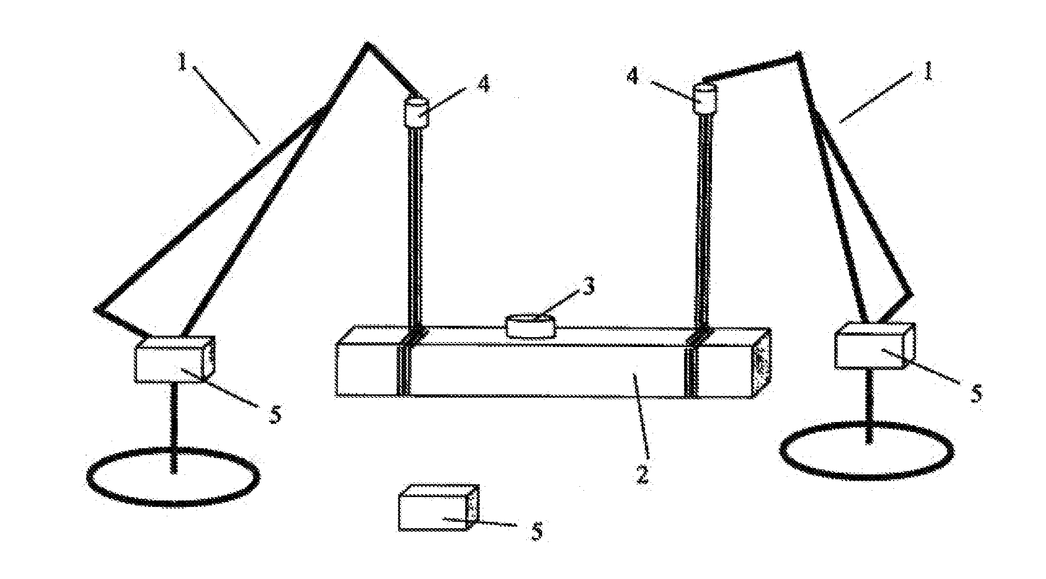
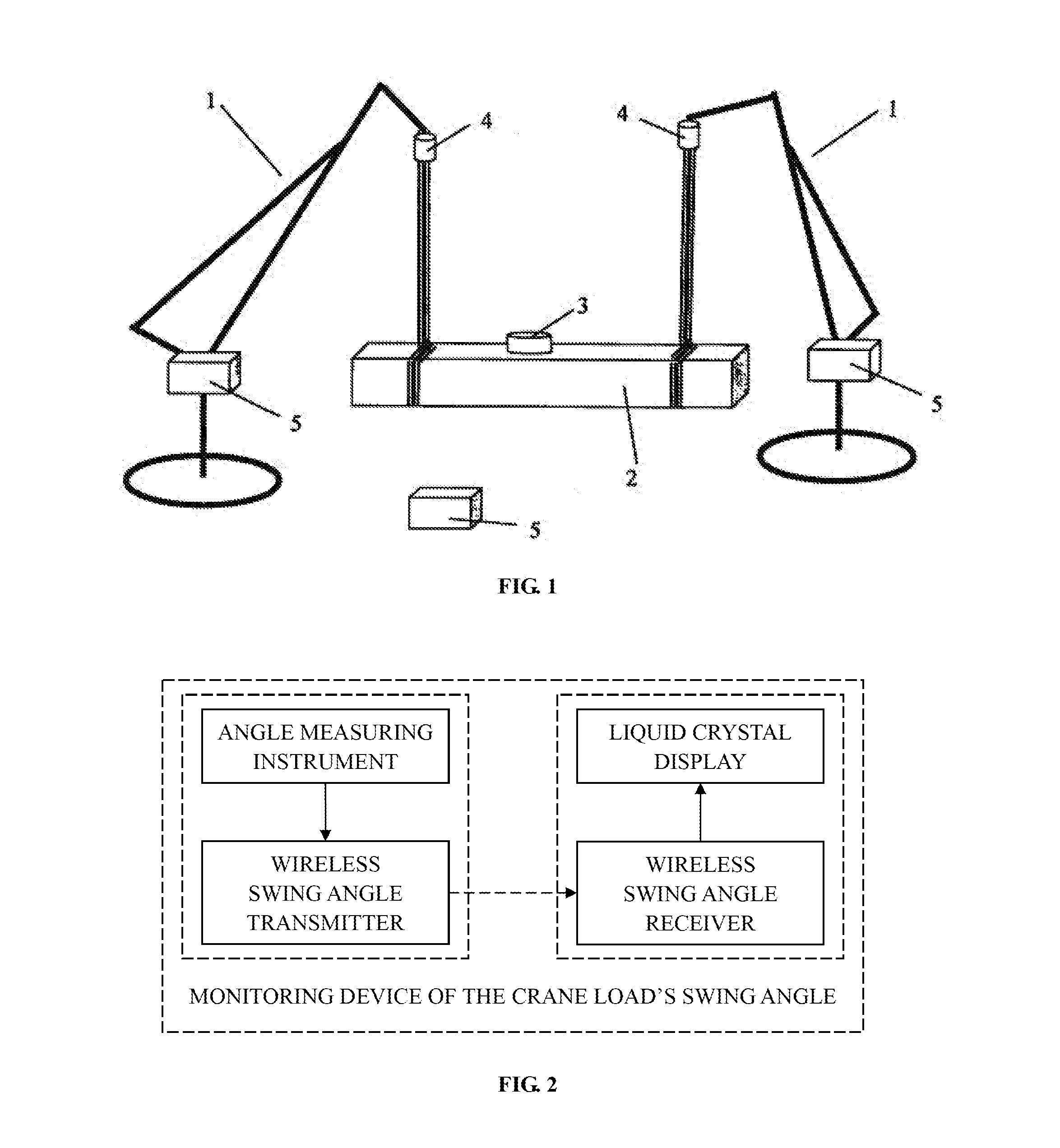
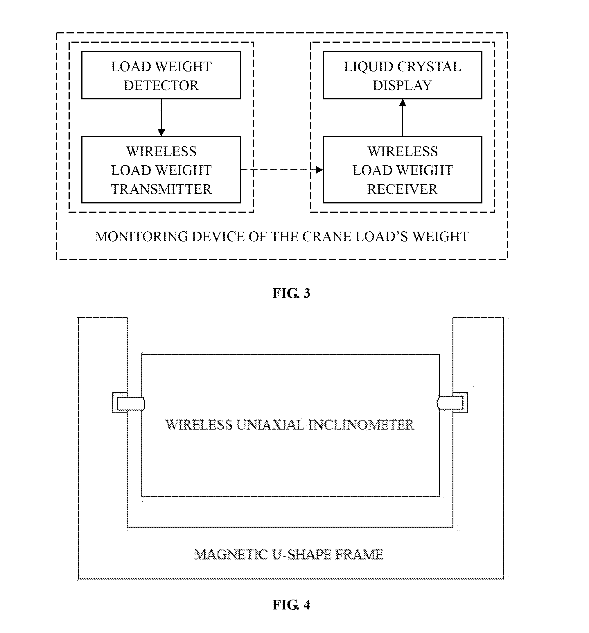
[0026]First, there is disclosed an apparatus for monitoring the swing angle and weight of the crane load, comprising:

(1) a monitoring device of the crane load's swing angle installed as follows:

① firstly, respectively extending 30 cm of the two sides of the guard plate of the movable pulley of the lifting pulley block of the mobile crane; secondly, there is also a beam fixed on the bottom of the guard plate; thirdly, a hook is fixed on the beam by the nut, which can rotate around the axis of the hook's handle with bearings. As the distance between the movable pulley and the hook's head is widen, there is a space provided to install an angle measuring instrument which is located on the inside vacancy between the two length-extended sides of the guard plate. Meanwhile, the two sides of the guard plate can be made of fiber reinforced plastics in order to reduce the surrounding strong magnetic interference and benefit the wireless emission of the measured signal.

② fixing a nonmagnetic p...


PUM


Abstract

Disclosed in the present invention is a crane, method and apparatus for monitoring the swing angle, weight or gesture of the crane load, belonging to the technical field of crane; the purpose of the present invention is provide an apparatus for monitoring the swing angle, weight or gesture for the crane's hoisting, and to provide a crane which comprises aforesaid apparatus; when hoisting a load, the swing angle, weight or gesture are displayed in both the native crane cab and the collaborative crane cab by wireless transmission and switching channels in the cab; then, not only can the drivers operate the cranes to eliminate the deflection of load and achieve the vertical hoisting according to the load's swing angle of each crane displayed on the screen, but also operate the cranes to make balance of weight distribution according to the real-time ratio of load weight or load gesture.

Description

[0001]This application claims priority to PCT Application No. PCT / CN2014 / 073961 filed on Mar. 24, 2014, which claims priority to China patent No. 201310249688.2 filed on Jun. 21, 2013 and granted on Jan. 7, 2015, which are incorporated in their entirety herein by reference.FIELD OF THE INVENTION[0002]The present application relates to the technical field of crane, and more specifically to a crane, method and apparatus for monitoring the swing angle, weight or gesture of the crane load.BACKGROUND OF THE INVENTION[0003]The crane requires vertical lifting as the deviation angle of hook shall not exceed 3 degrees when a work-piece is lifted by the mobile crane, but the driver cannot determine whether the hook is in the vertical position for lack of the display on the crane to show vertical hoisting. Especially when collaboratively hoisting, the hoisting commander instructs the drivers to operate and eliminate the load's swing angle with the information from whom monitors the load's angl...

Claims


Application Information

Patent Timeline
Patent Type & Authority Applications(United States)
IPC IPC(8): B66C13/16G01G19/14G01C9/02B66C13/18
CPCB66C13/16G01C9/02G01G19/14B66C13/18B66C13/06G01C21/34B66C23/00
Inventor LIN, HANDING
Owner LIN HANDING
Why Eureka
Try Eureka