Image forming device

Inactive Publication Date: 2007-04-26
KYOCERA DOCUMENT SOLUTIONS INC
View PDF2 Cites 19 Cited by
  • Summary
  • Abstract
  • Description
  • Claims
  • Application Information

AI Technical Summary

Benefits of technology

[0011] In the present invention, thus, the cover member protects the intermediate transfer belt at a position corresponding to the nip when in a protected position, and when in a withdrawn position, the cover member guides the recording paper, while the interlocking mechanism, moving in response to the turning of the cover body, places the cover member at the protected position upon the paper transport path becoming exposed when the cover body (lateral cover) is opened, and places the cover member at the withdrawn position when the cover body is closed; as a result, the user is prevented from inadvertently touching the intermediate transfer belt when the cover body is opened to remove recording paper jammed in the paper transport path, since the intermediate transfer belt is protected by the cover member.
[0012] In the present invention, the withdrawn position is further downstream in the recording paper transport direction than the nip, one end of the supporting member is turnably supported on

Problems solved by technology

Thus, when the intermediate transfer belt is exposed for handling a paper jam, the user may inadvertently touch the intermediate transfer belt, which might result in faulty imaging.
In conventional image forming devices, when the lateral cover is opened, the photosensitive drum, which is the image carrier, is protected by the drum shutter, while when the lateral cover is closed, the drum shutter is positioned further upstream in the paper transport direction than the photosensitive drum, the role of the drum shutter being to guide the recording paper being transported along the pa

Method used


Image

  • Image forming device
  • Image forming device
  • Image forming device

Examples


embodiment 1

[0024] Embodiment 1

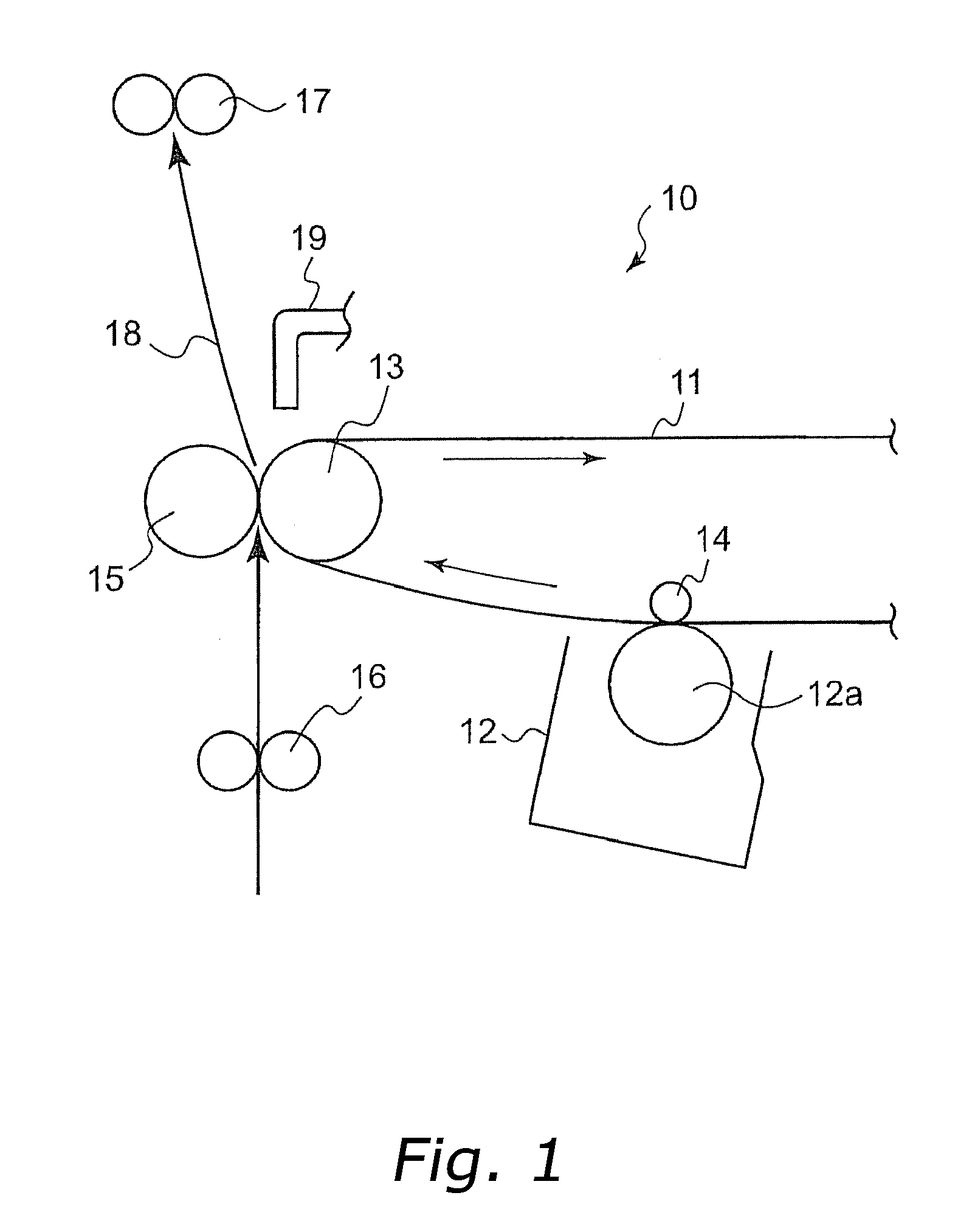
[0025]FIG. 1 is a view illustrating schematically a portion of an image forming device according to the present invention; the image forming device 10 in the figure has an intermediate transfer belt 11, and image forming units 12 for each color arranged below and along the intermediate transfer belt 11 (only one image forming unit 12 is depicted in FIG. 1).

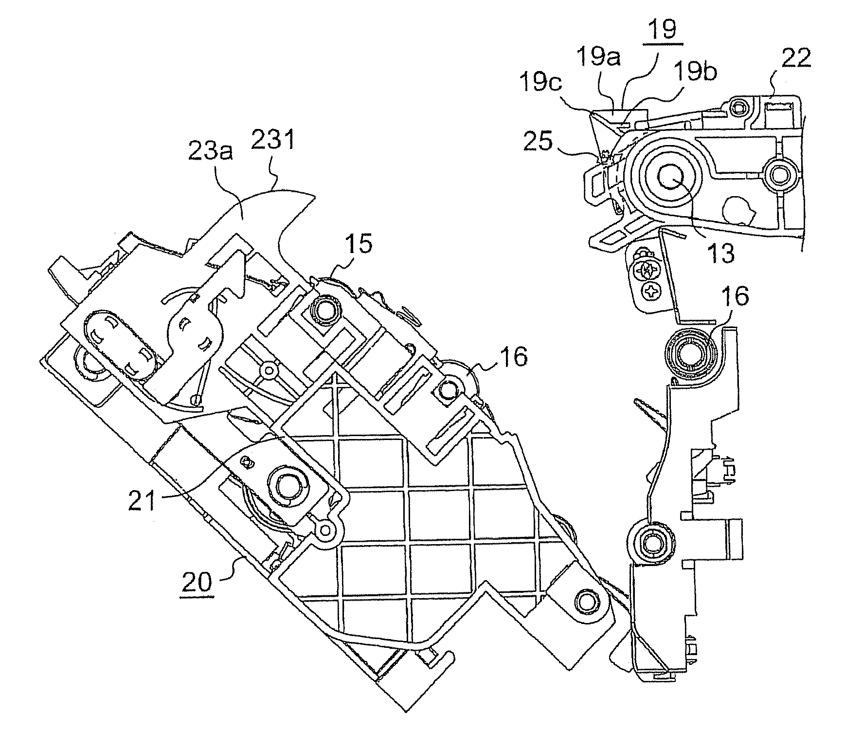
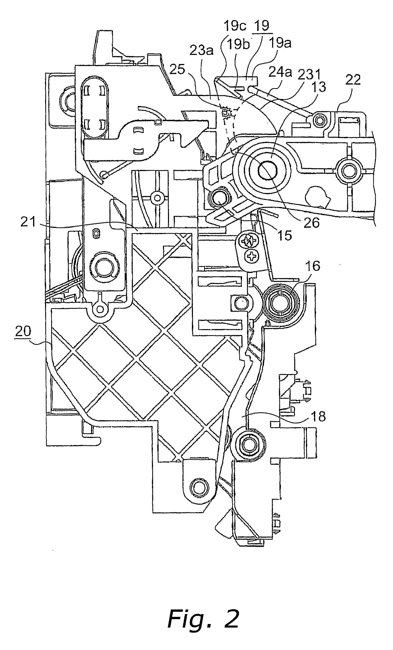
[0026] The intermediate transfer belt 11 is stretched tightly by a driving roller 13, a driven roller (not shown in the figure), and the like, and a photosensitive drum 12a of the image forming unit 12 is arranged opposite the primary transfer roller 14, flanking the intermediate transfer belt 11. A secondary transfer roller (transfer unit) 15 is arranged facing the driving roller 13; as shown in the figure, a substantially vertical paper transport path 18 is defined as transiting the registration rollers 16, the nip between the intermediate transfer belt 11 and the secondary transfer roller 15, and the fixing ...


PUM


Abstract

A toner image formed on a photosensitive drum 12a in an image forming unit 12 is transferred to an intermediate transfer belt 11. The toner image of the intermediate transfer belt is transferred onto recording paper by a transfer roller 15, and a paper transport path 18 is defined by an image forming device main body and a lateral cover 20 turnably mounted on the image forming device main body 20. When in a protected position, a cover member 19 protects the intermediate transfer belt at a position corresponding to a nip between the intermediate transfer belt and a transfer unit, while when in a withdrawn position, the cover member 19 guides the recording paper. An interlocking mechanism, moving in response to the turning of the lateral cover, places the cover member at the protected position when the lateral cover is open, and places the cover member at the withdrawn position when the lateral cover is closed.

Description

FIELD OF THE INVENTION [0001] The present invention relates to an image forming device such as a copying machine, a printer, a fax device or the like, and more particularly to an image forming device comprising an intermediate transfer belt, wherein a toner image formed on the intermediate transfer belt is transferred onto recording paper. BACKGROUND INFORMATION [0002] In color image forming devices, image formation is generally carried out by forming color toner images by sequentially superposing toner images of each color on an intermediate transfer belt and then transferring the color toner image onto recording paper; in such image forming devices, the recording paper is transported from a paper feeding unit to a nip between the intermediate transfer belt and a secondary transfer roller, via a paper transport path, then after transfer of the color toner image to the recording paper, the latter is sent via the paper transport path to a fixing unit, and following color toner image ...

Claims


Application Information

Patent Timeline
IPC IPC(8): G03G21/00
CPCG03G21/16G03G2221/1642G03G2221/1687G03G21/1638
Inventor ITO, HIROSHI
Owner KYOCERA DOCUMENT SOLUTIONS INC
Why Eureka
Try Eureka