Non-aggressive anchor washer

a washer and non-aggressive technology, applied in the direction of washers, snap-action fasteners, dental implants, etc., can solve the problems of affecting the operation of the washer

Inactive Publication Date: 2007-04-26
LEGRIS
View PDF8 Cites 7 Cited by
  • Summary
  • Abstract
  • Description
  • Claims
  • Application Information

AI Technical Summary

Benefits of technology

[0015] Furthermore, the anchor washer is generally fitted to the tubular body of the coupling device. More precisely, the anchor washer is received in a groove of the tubular body. Mounting the washer then requires the body to be in two portions that are generally snap-fastened together, thereby increasing the cost of manufacturing the tubular body. Furthermore, the anchor washer is free in rotation relative to the body and can then pivot relative to the first duct, and that can be harmful in certain applications, while adding indexing means makes manufacture more complicated. In general, fastening the anchor washer to the body is difficult and in certain configurations there exists a risk of the coupling member becoming lost before the coupling device is mounted in the first duct. To solve this problem, it is possible to overmold the tubular body on the anchor member. However that increases the cost of manufacturing the tubular body.
[0017] Thus, the layer of plastics material serves firstly to secure the anchor washer to the tubular body, and secondly it ensures that contact between the tooth and the thread avoids machining the thread which might generate shavings that would run the risk of polluting the fluid being transported or the risk of damaging devices connected to the fluid transport circuit downstream from the coupling device.

Problems solved by technology

Nevertheless, it has been found that the teeth of anchor washers subject the thread to wear or damage leading to particles or even shavings being detached therefrom (particularly if the wall of the duct is made of a plastics material) or else it files the thread down (if the wall of the duct is made of metal), thereby polluting the fluid that is transported and running the risk of damaging a circuit element connected downstream from the coupling device.
Experiments have shown that this wear or damage results from the crest of the thread being bitten into by the side edges of the surfaces of the teeth that face towards the thread and that do not have their end surfaces bearing against the flank of the thread.
Even if the teeth are less aggressive in the first configuration, the wear they generate is nevertheless too great.

Method used


Image

  • Non-aggressive anchor washer
  • Non-aggressive anchor washer
  • Non-aggressive anchor washer

Examples


first embodiment

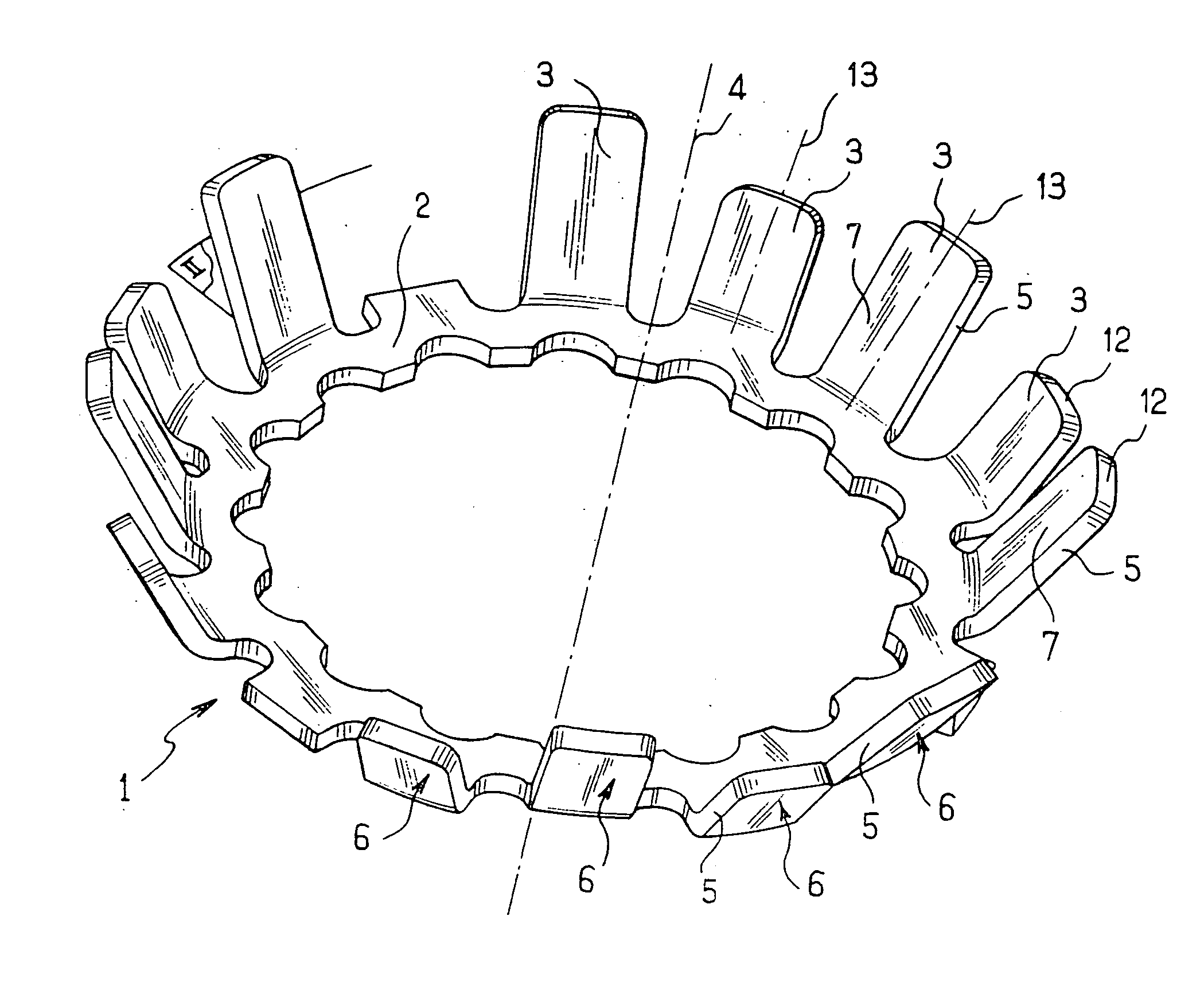
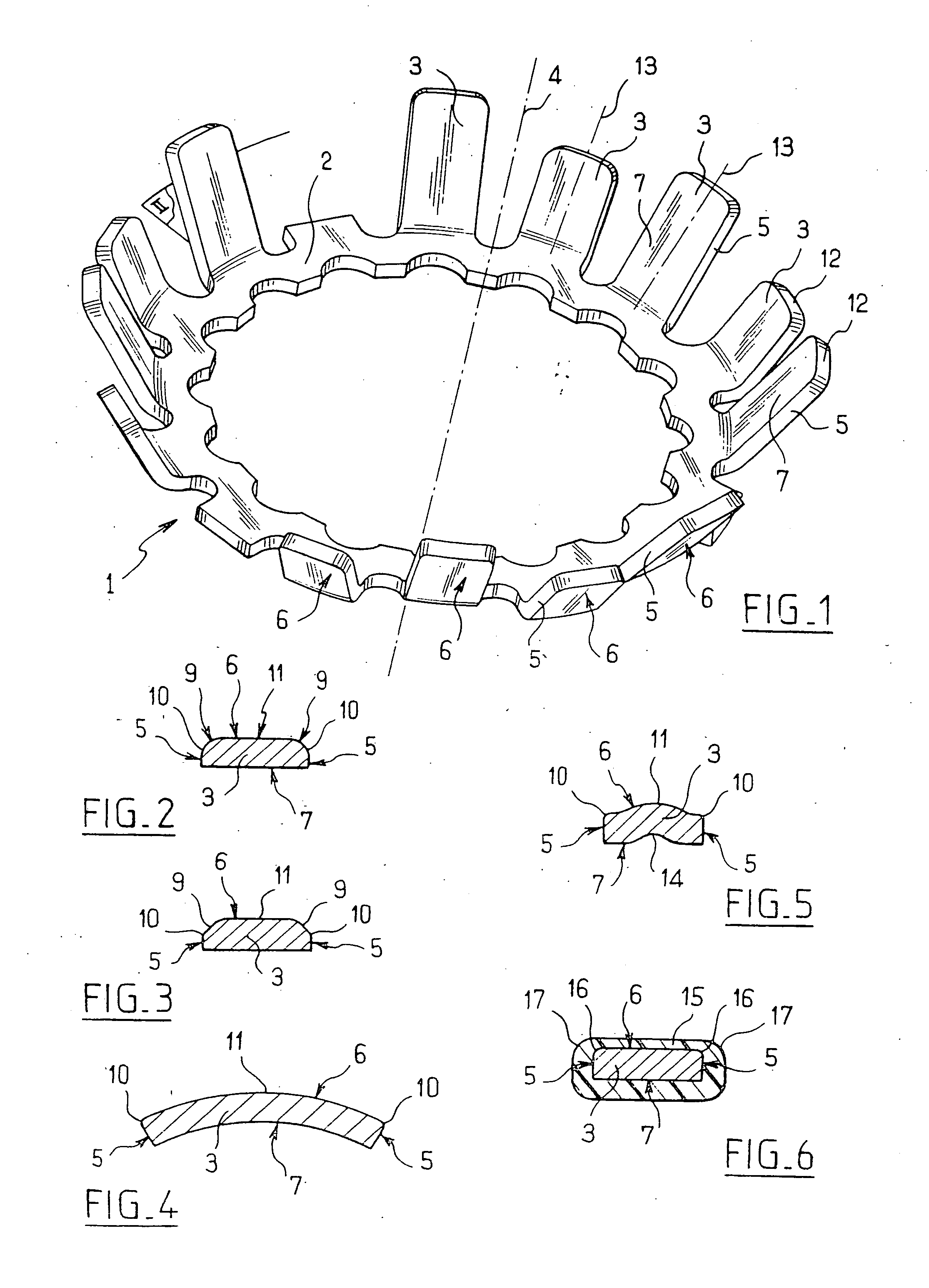
[0025] With reference to FIGS. 1 and 2, the anchor washer constituting the invention, given overall reference 1, comprises an annular portion 2 having an outer circumference from which teeth 3 extend outwards. These teeth 3 are inclined relative to a central axis 4 of the annular portion 2. Each tooth 3 comprises two side faces 5 between which there extends a surface 6 (this surface is referred to below as the “sliding” surface 6) facing away from the central axis 4, and an opposite surface 7 facing the central axis 4. The sliding surface 6 has rounded end portions 9 connected to edges 10 connecting with the side faces 5 (the end portions 9 are not visible in FIG. 1). The edges 10 are thus set back from the central portion 11 of the sliding surface 6. Each tooth further comprises an end surface or terminal surface 12. The anchor washer 1 is made of metal, in this case of steel.

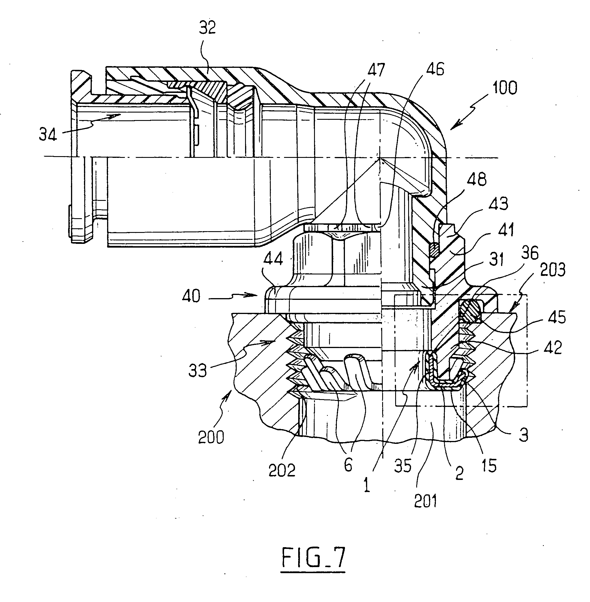
[0026] The anchor washer 1 is for fitting to a coupling device comprising a tubular body having a first con...

second embodiment

[0029] In a second embodiment shown in FIG. 3, the end portions 9 are shaped by chamfers. The edges 10 are thus set back from the central portion 11 of the sliding surface 6.

third embodiment

[0030] In a third embodiment shown in FIG. 4, the teeth 3 are curved about a longitudinal axis 13 of each tooth 3 so that the sliding surface 6 presents convex curvature. The edges 10 are thus set back from the central portion 11 of the sliding surface 6.


PUM


Abstract

An anchor washer for anchoring a first element and a second element in relative engagement, includes an annular portion from which there extends at least one tooth that is inclined relative to a central axis of the annular portion, the annular portion being designed for mounting on the first element, and the tooth having two side faces between which there extends a rubbing surface for being oriented substantially towards the second element, the surface being connected to the side faces via coupling portions, the tooth being shaped so that at least one of the coupling portions is set back from at least a portion of the surface so that the coupling portion is kept at a distance from the second element. A coupling device including such a washer is also disclosed.

Description

[0001] The present invention relates to an anchor washer for anchoring a first element to a second element engaged relative thereto. By way of example, the first element is an end portion of a coupling device and the second element is constituted, for example, by a tapped end portion of a duct. The invention also provides a coupling device fitted with such a washer. BACKGROUND OF THE INVENTION [0002] The anchor washer generally comprises an annular portion from which there extend teeth that are inclined relative to a central axis of the annular portion. The annular portion is mounted on the end portion of the coupling device and each tooth has two side faces between which there extends a surface that faces towards the thread of the tapped end portion of the duct. The coupling device is installed by engaging the end portion of the coupling device in the tapping. The coupling device is retained by one or more teeth having free ends that bear against the flank of the thread, with the o...

Claims


Application Information

Patent Timeline
Patent Type & Authority Applications(United States)
IPC IPC(8): A61C8/00
CPCF16B21/08F16B21/18F16B43/00F16L37/091F16L37/0915
Inventor LE BARS, NICOLAS
Owner LEGRIS
Why Eureka
Try Eureka