Electrical Component, in Particular Relay Socket, Having Spring Clamps, and Method for the Manufacture Thereof

Active Publication Date: 2007-04-26
TYCO ELECTRONICS AUSTRIA
View PDF3 Cites 17 Cited by
  • Summary
  • Abstract
  • Description
  • Claims
  • Application Information

AI Technical Summary

Benefits of technology

[0004] It is therefore an object of the invention is to provide an electrical component, such

Problems solved by technology

Disadvantageously, this type of terminal not only requires a tool to actuate the clamp but also the clamping step is timely.
Moreover, it is very difficult to insert and cl

Method used


Image

  • Electrical Component, in Particular Relay Socket, Having Spring Clamps, and Method for the Manufacture Thereof
  • Electrical Component, in Particular Relay Socket, Having Spring Clamps, and Method for the Manufacture Thereof
  • Electrical Component, in Particular Relay Socket, Having Spring Clamps, and Method for the Manufacture Thereof

Examples


Example

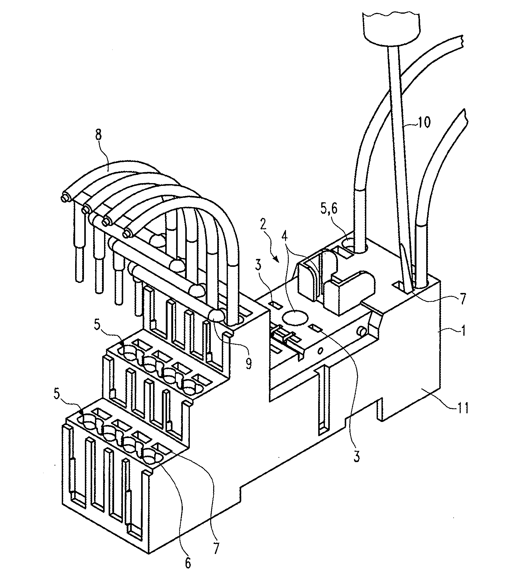
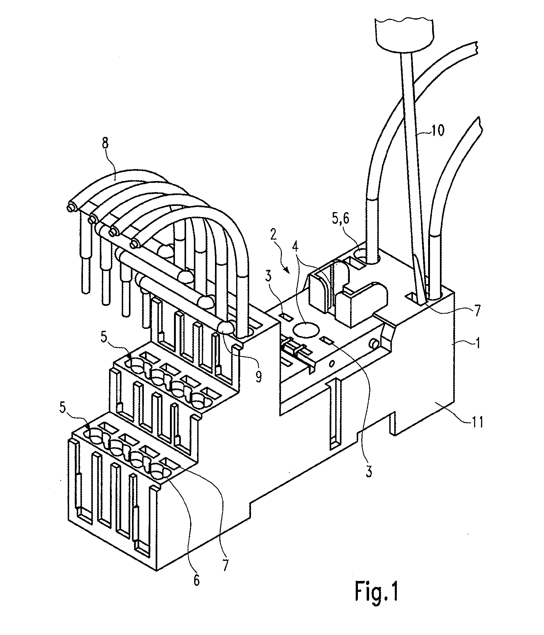
[0011]FIG. 1 shows an electrical component according to the invention. As shown in FIG. 1, the electrical component in the illustrated embodiment is configured as a relay socket 1. The relay socket 1 has a receiving region 2 configured for receiving a relay (not shown). The receiving region 2 includes plug contacts 3 configured for receiving pins (not shown) of the relay (not shown) and positioning devices 4 configured for precisely positioning the relay (not shown) in the receiving region 2.

[0012] As shown in FIG. 1, a plurality of terminals 5 are connected by conductor elements 18 (FIG. 2) to the plug contacts 3. Each of the terminals 5 is provided with at least one insertion opening 6 and at least one actuation opening 7. Alternatively, a single actuation opening 7 may be provided that extends adjacent to all of the insertion openings 6. At least one conductor 8 and / or at least one linking member 9 may be received in the insertion openings 6. An internal contour of the insertion...


PUM


Abstract

An electrical component, such as a relay socket, comprises a housing having at least one terminal provided with an insertion opening configured for receiving at least one conductor end. The insertion opening communicates with an assembly chamber formed in the terminal. A clamping device is arranged in the assembly chamber. The clamping device has a leaf spring divided into substantially parallel spring contacts by a parting slot. Each of the spring contacts is deflectable in a direction of insertion of the conductor end and has a free end positioned adjacent to a contact pressure plate such that a clamping slot is formed there between that force-fittingly receives the conductor end. A conductor element may additionally extend from the clamping device and be force-fittingly connected between the free ends of the spring contacts and the contact pressure plate to form a single piece pre-assembled unit with the clamping device.

Description

FIELD OF THE INVENTION [0001] The invention relates to an electrical component, such as a relay socket, having a housing and at least one terminal for connecting at least one conductor end. The terminal is provided with at least one insertion opening which extends in a direction of insertion of the conductor end into the housing and a clamping device which allows the conductor end to be force-fittingly fixed in a conductor receiving chamber therein. BACKGROUND OF THE INVENTION [0002] Electrical components that have a housing and at least one terminal for connecting at least one conductor end are known from the prior art. Traditionally, screw clamps or strain relief clamps are used to connect the conductor ends when the conductor end is introduced into a clamping slot delimited by an electrically conductive contact pressure plate. The contact pressure plate is pressed onto the conductor end by the clamp to narrow the clamping slot and electrically connect the conductor end to the com...

Claims


Application Information

Patent Timeline
IPC IPC(8): H01R12/24
CPCH01H50/14H01R4/4827H01R9/26H01R43/20H01R4/48275
Inventor HELMREICH, JOHANNES
Owner TYCO ELECTRONICS AUSTRIA
Why Eureka
Try Eureka