
Adjustable interbody introducer device and method

a technology of introducer and introducer, which is applied in the direction of osteosynthesis devices, internal osteosynthesis, prosthesis, etc., can solve the problems of damage to the annulus, the outer ring that holds the disc together, and the nucleus pulposus beginning to lose its water content, so as to achieve the effect of easy disengagement and removal

Active Publication Date: 2007-04-26
K2M
View PDF25 Cites 158 Cited by
  • Summary
  • Abstract
  • Description
  • Claims
  • Application Information

AI Technical Summary

Benefits of technology

[0008] The present invention meets the above identified need by providing a novel surgical instrument device that effectively engages an interbody for introduction of the interbody into an intervertebral space and after positioning that interbody can be easily disengaged and removed from the surgical site.
[0009] Also provided is a device having an adjustable angle distal end for introducing an interbody into an intervertebral space wherein the distal end of the device is provided with an interbody grasping unit that can securely grasp the interbody for the process of implanting the interbody and, upon completion of the introduction, can be easily disengaged from the implanted interbody.
[0012] Also provided is a method of introducing an interbody into an intervertebral space using a device having an adjustable angle distal end, the distal end being capable of securely connecting to the interbody prior to the implantation of the interbody and easily releasing from the interbody after the interbody is implanted in a subject.

Problems solved by technology

Excessive pressure or injuries to the disc can cause injury to the annulus—the outer ring that holds the disc together.
Eventually this can lead to damage of the nucleus pulposus.
The nucleus begins to lose its water content due to the damage—it begins to dry up.
Because of water loss, the discs lose some of their ability to act as a cushion.
This can lead to even more stress on the annulus and still more tears as the cycle repeats itself.
This results in a narrowing of the disc space between the two vertebrae.
This shift changes the way the facet joints work together and can cause problems in the facet joints as well.
A major challenge of spine surgery is in the development of surgical instruments for the surgeon to use during the implantation of the devices such as an artificial disc replacement or interbody.

Method used


Image

  • Adjustable interbody introducer device and method
  • Adjustable interbody introducer device and method
  • Adjustable interbody introducer device and method

Examples


Embodiment Construction

[0023] Detailed embodiments of the present invention are disclosed herein; however, it is understood that the following description and each of the accompanying figures are provided as being exemplary of the invention, which may be embodied in various forms without departing from the scope of the claimed invention. Thus, the specific structural and functional details provided in the following description are non-limiting, but serve merely as a basis for the invention as defined by the claims provided herewith. The device described below can be modified as needed to conform to further development and improvement of materials without departing from the inventor's concept of the invention as claimed.

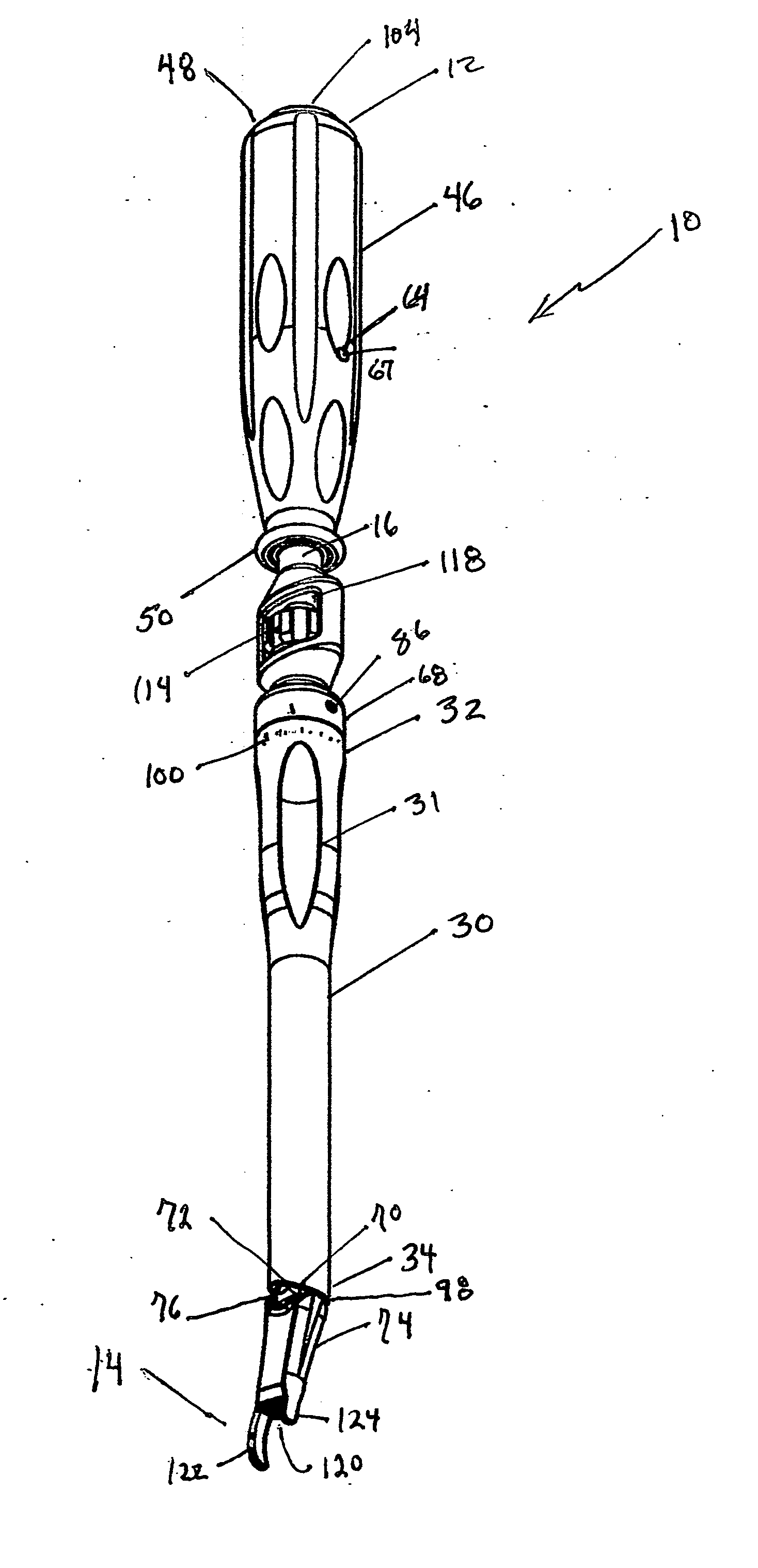
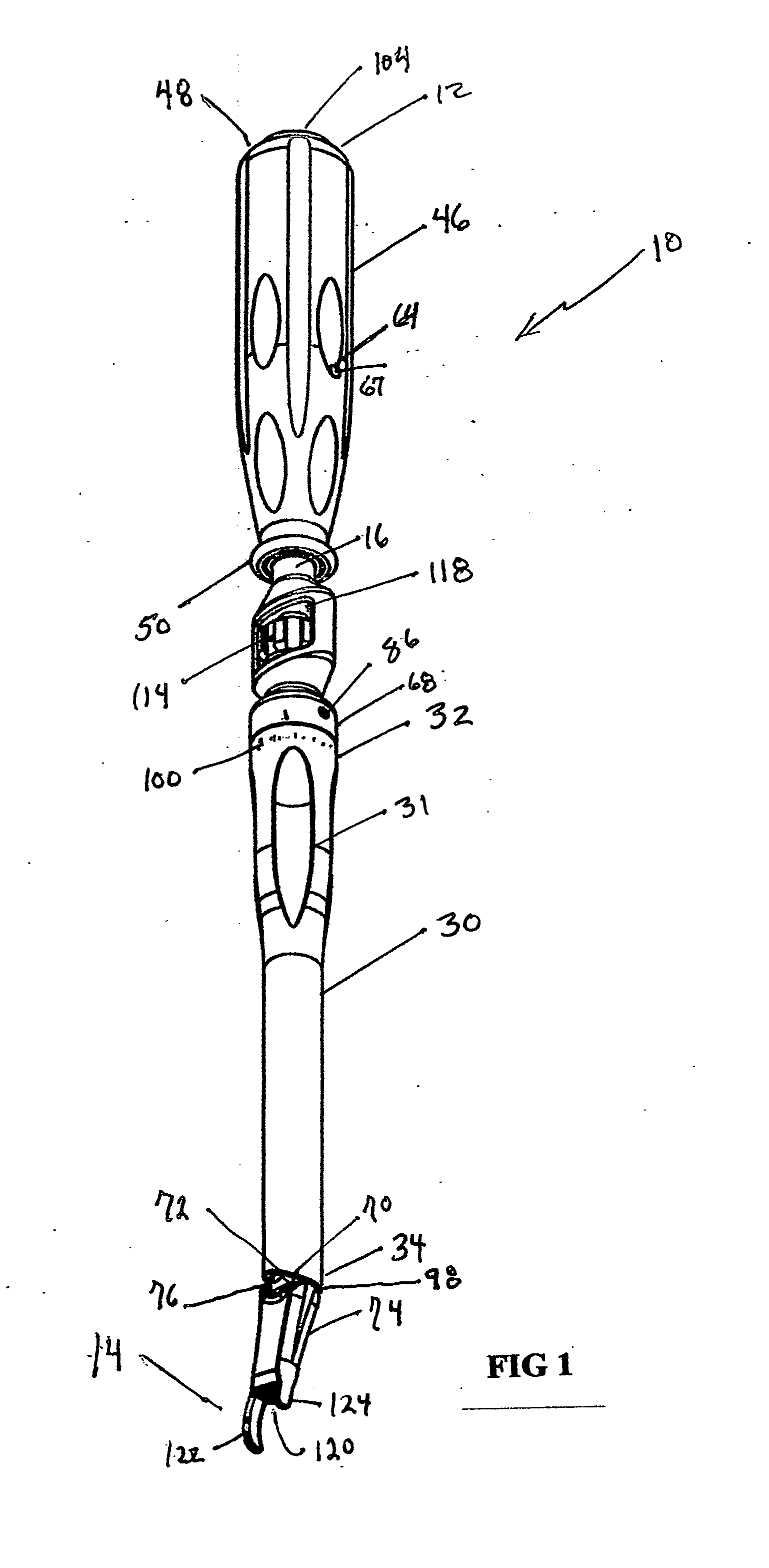
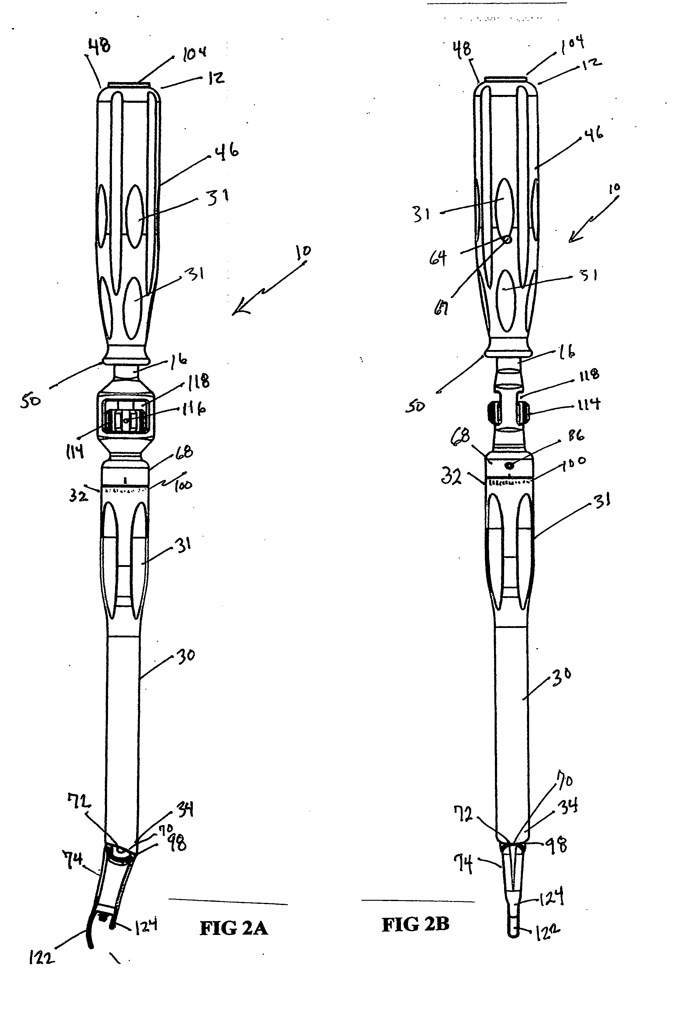
[0024] The device, as generally shown at 10 in FIGS 1, 2A-B, 4, 5 and 8A-C is an interbody introducer having an adjustable angle distal end. The device 10 has a proximal first end 12 and a distal second end 14. As shown in FIG. 4, the device 10 includes a tubular inner shaft 16 having a pr...


PUM


Abstract

Provided is a novel surgical instrument having an adjustable distal end that can securely engage an interbody for introduction of the interbody into an intervertebral space, can be adjusted before and during the surgical procedure to vary the angle of the distal end of the device and the angle of introduction of the interbody, and after positioning that interbody at the surgical site, can be easily disengaged and removed.

Description

BACKGROUND OF THE INVENTION [0001] 1. Technical Field [0002] The present invention relates to devices and methods for use in orthopedic spine surgery. In particular, the present invention relates to a device having at least two distinct articulating surfaces, the device being useful as an artificial disc replacement and a method of implanting that device using a posterior approach. [0003] 2. Background Art [0004] The human spine is comprised of thirty-three vertebrae at birth and twenty-four as a mature adult. Between each pair of vertebrae is an intervertebral disc, which maintains the space between adjacent vertebrae and acts as a cushion under compressive, bending and rotational loads and motions. A healthy intervertebral disc has a great deal of water in the nucleus pulposus—the center portion of the disc. The water content gives the nucleus a spongy quality and allows it to absorb spinal stress. Excessive pressure or injuries to the disc can cause injury to the annulus—the oute...

Claims


Application Information

Patent Timeline
IPC IPC(8): A61F2/00H05B44/00
CPCA61F2002/30471A61F2002/30505A61F2002/30538A61F2002/30601A61F2002/4624A61F2002/4627A61F2002/4628A61F2002/4629A61F2002/4681A61F2220/0025A61F2220/0091A61F2230/0015A61F2250/0006A61B17/7001A61B17/7059A61F2/4455A61F2/4611A61F2002/30133A61F2/4603H05B47/16H05B47/11Y02B20/40
Inventor HARRIS, PETER M.MCCLINTOCK, LARRY E.WALLENSTEIN, TODD M.STRAUSS, KEVIN R.
Owner K2M
Learn More