
Multi-tweezer hair removal apparatus and method

a hair removal and multi-tweezer technology, applied in the field of hair removal apparatus and method, can solve the problems of hair trapped, disc mechanism subject to constraints, and number of tweezers to be limited, and achieve the effect of less production accuracy and low for

Inactive Publication Date: 2007-04-26
EPILADY 2000 LLC
View PDF9 Cites 13 Cited by
  • Summary
  • Abstract
  • Description
  • Claims
  • Application Information

AI Technical Summary

Benefits of technology

[0011] According to an aspect of the present invention, an epilating device in provided in which relatively low forces and less production accuracy are required for operation while a relatively large number of tweezers may be employed.

Problems solved by technology

When the tweezers are closed, hair is trapped.
However, these disc mechanisms may be subject to constraints.
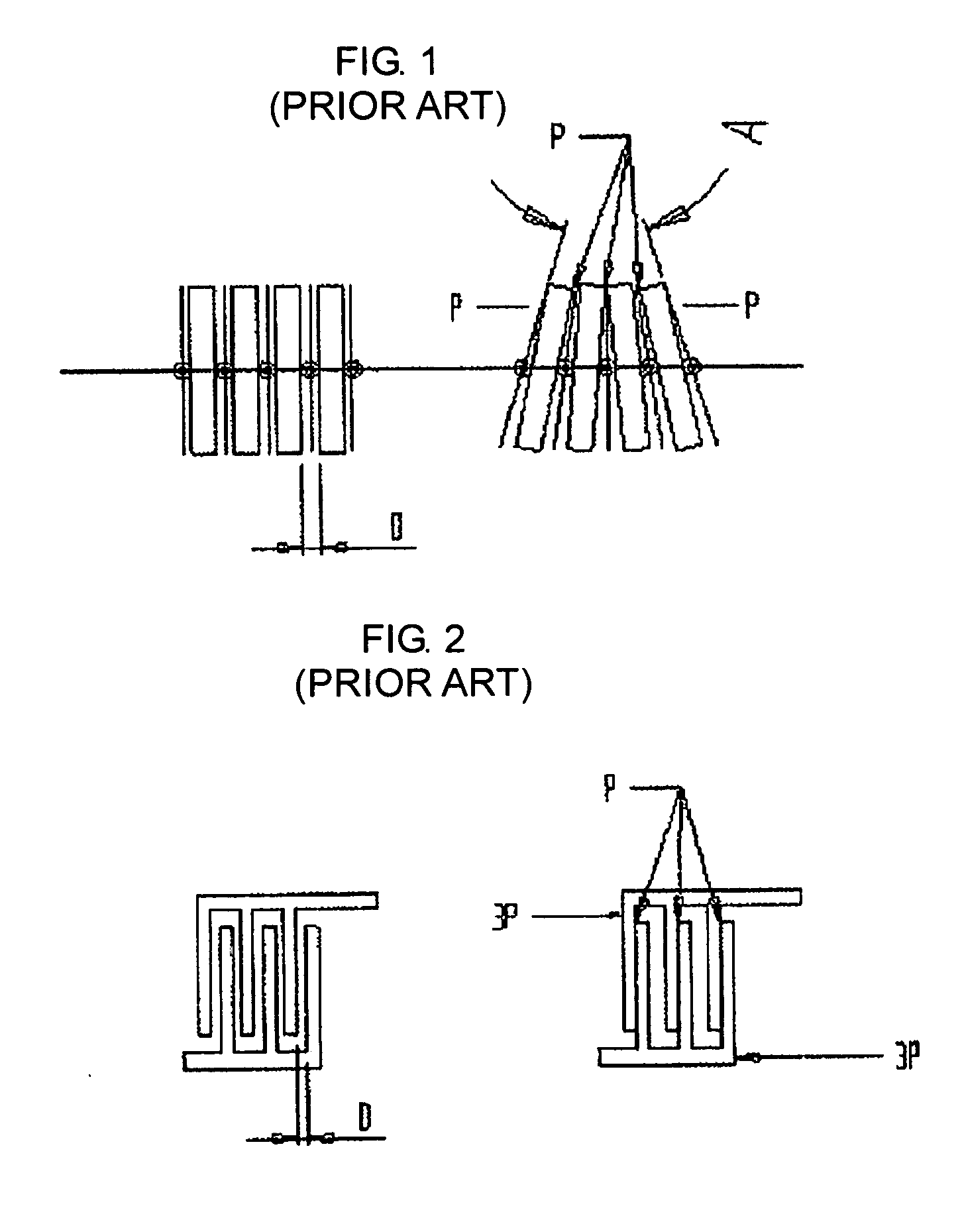
However, in order to obtain the optimal angle for a tweezing operation, as shown in FIG. 1, the number of tweezers must be limited.
However, due to technical limitations, the number of tweezers must be kept relatively low.

Method used


Image

  • Multi-tweezer hair removal apparatus and method
  • Multi-tweezer hair removal apparatus and method
  • Multi-tweezer hair removal apparatus and method

Examples


Embodiment Construction

[0028] Reference will now be made in detail to the present embodiments of the present invention, examples of which are illustrated in the accompanying drawings, wherein like reference numerals refer to the like elements throughout. The embodiments are described below in order to explain the present invention by referring to the figures.

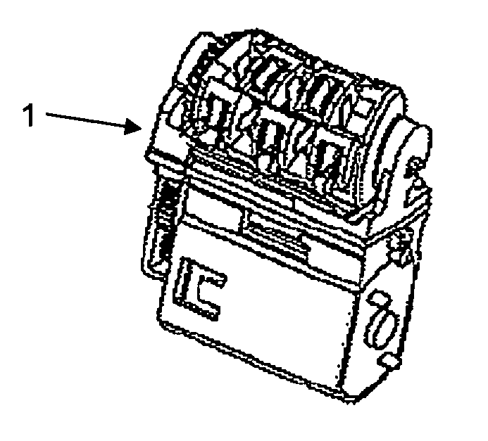
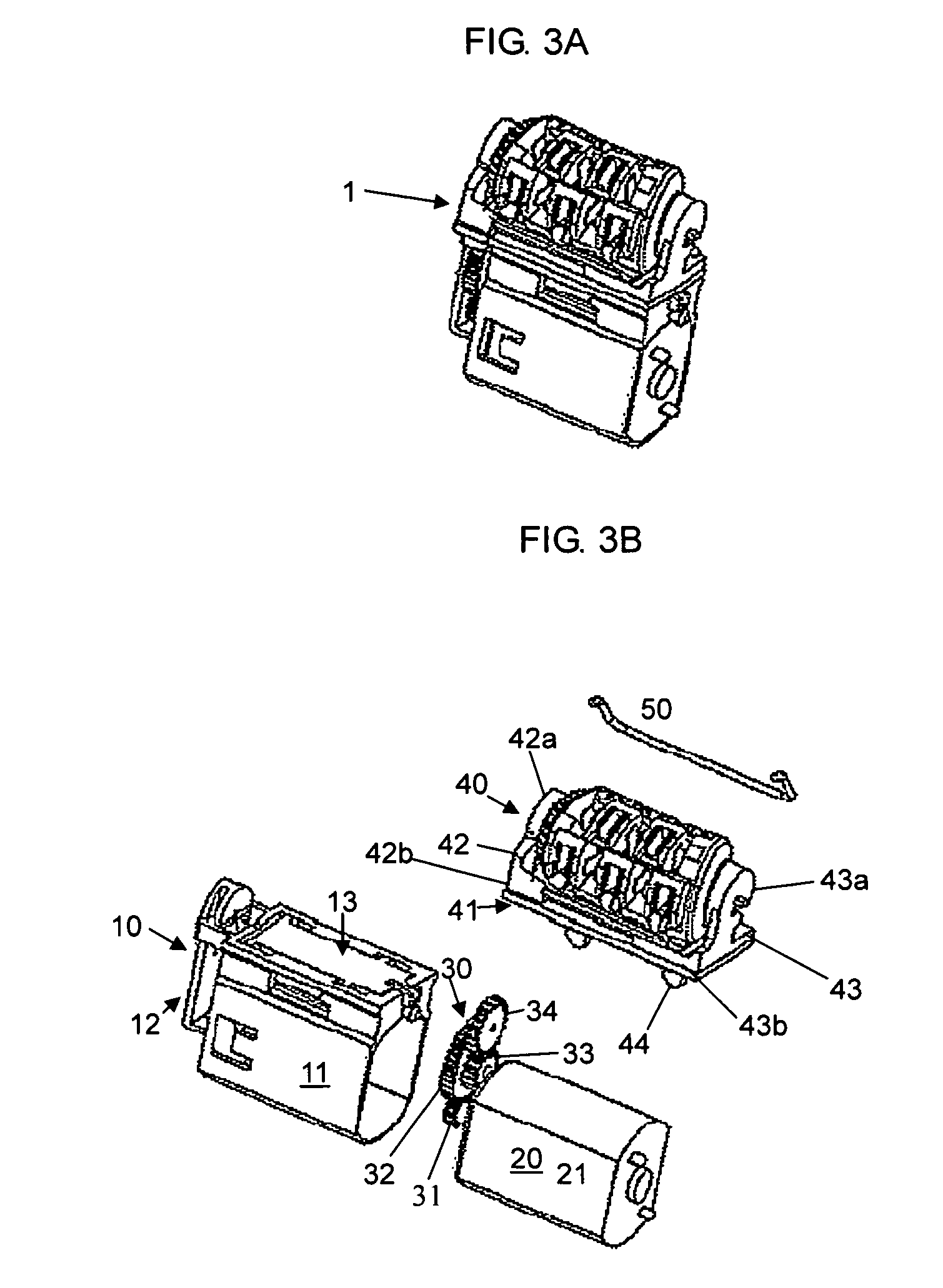
[0029] With reference to FIGS. 3A and 3B, an epilating device 1 according to an embodiment of the present invention includes a frame 10, a power source 20, a reduction gear system 30, an epilating unit 40, and a spring 50. The frame 10 includes a power source frame 11, a reduction gear frame 12, and a base 13. The power source frame 11 and the reduction gear frame 12 each define an interior that is of sufficient size and shape to tightly fit around the power source 20 and the reduction gear system 30, respectively. The base 13 rests at one end of the power source frame 11 and communicates with both the power source frame 11 and the reduction gear fra...


PUM


Abstract

An epilating device to remove hair, including a frame including a power source frame, a reduction gear system frame, and a base, a power source supported in the power source frame to provide power to the hair removing operation, a reduction gear system supported in the reduction gear frame to transfer power from the power source to the base, and an epilating unit supported by the base. The epilating unit includes a plurality of epilators tightly aligned in a column along a curved shaft, each epilator having a set of tweezers disposed with respective tweezing ends radially extending to be in line with an outer wall of the column, to rotate about the curved shaft according to the power transferred by the reduction gear system. A curve in the curved shaft induces the tweezers to close when the tweezers pass along the outside of the curve during the rotation.

Description

BACKGROUND OF THE INVENTION [0001] An aspect of the present invention relates to a hair removal apparatus and method, and, more particularly, to a hair removing apparatus and method using an epilating device. DESCRIPTION OF THE RELATED ART [0002] In conventional hair removal devices there are generally one of two methods for removing hair available. According to the first method, the hair is cut, leaving the roots intact beneath the skin surface. According to the second method, sometimes referred to as epilation, hair is removed by pulling individual strands of hair out from their roots. [0003] Several of the proposed hair removal systems involve the use of tilted discs which come together at a point to grasp one or more strands of hair. Other mechanisms involve the use of cams to alternately bring the discs together and apart, thereby trapping strands of hair. Various such mechanisms are discussed in U.S. Pat. No. 4,935,024 to Dolev, U.S. Pat. No. 5,057,115 to Dolev, U.S. Pat. No. ...

Claims


Application Information

Patent Timeline
Patent Type & Authority Applications(United States)
IPC IPC(8): A61B17/50
CPCA45D26/0028
Inventor PORAN, YEHUDA
Owner EPILADY 2000 LLC
Learn More