System and method of AV interval selection in an implantable medical device

a medical device and av interval technology, applied in the field of implantable medical devices, can solve the problems of repeated process, limited or minimal time required for efficacious operation, and the ventricular pacing in the right ventricular apex may not be hemodynamically optimal for all patients

a medical device and av interval technology, applied in the field of implantable medical devices, can solve the problems of repeated process, limited or minimal time required for efficacious operation, and the ventricular pacing in the right ventricular apex may not be hemodynamically optimal for all patients

US20070093874A1Active Publication Date: 2007-04-26MEDTRONIC INC

Image

  • System and method of AV interval selection in an implantable medical device
  • System and method of AV interval selection in an implantable medical device
  • System and method of AV interval selection in an implantable medical device

Examples


Embodiment Construction

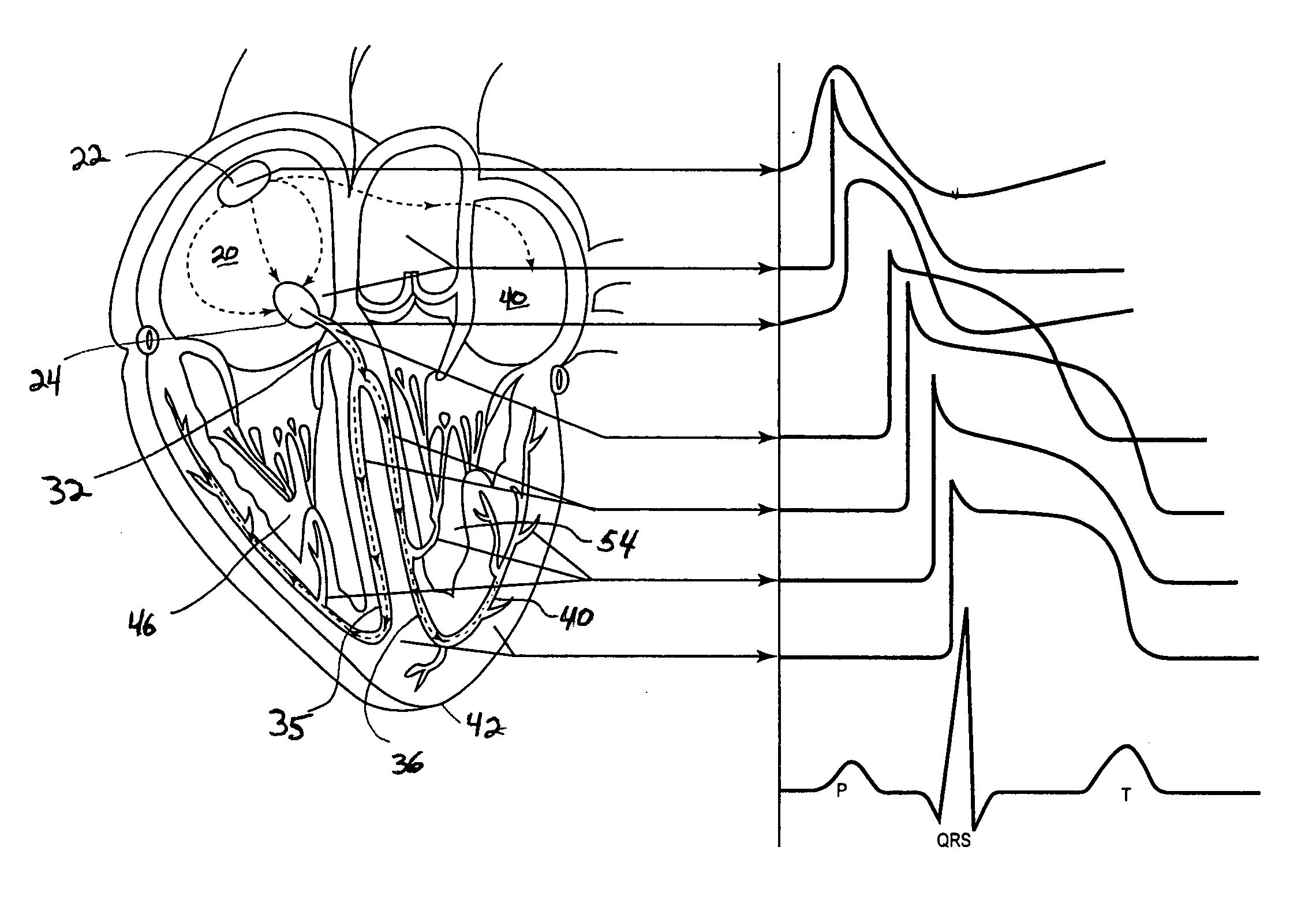
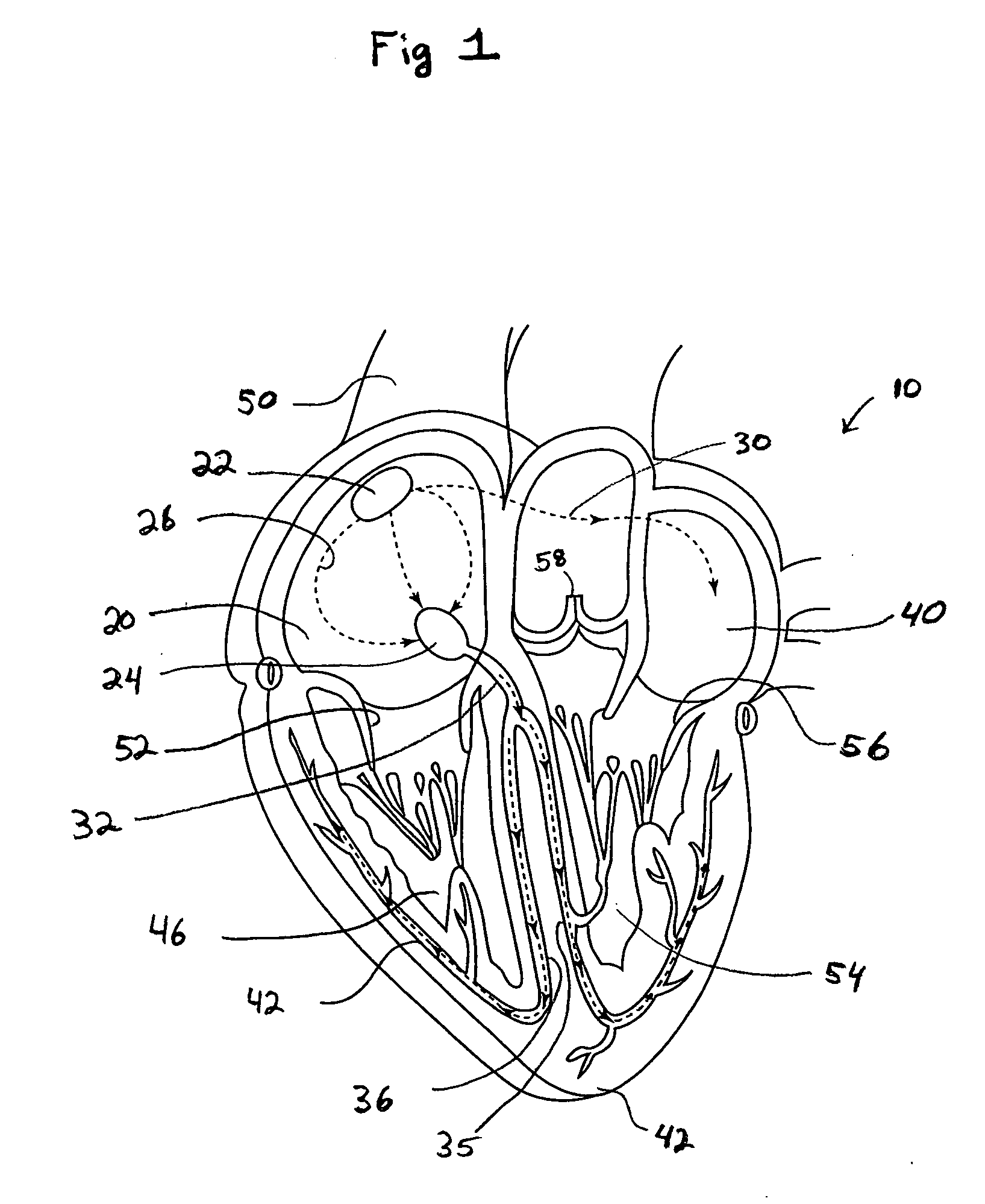
[0028]FIG. 1 is schematic, sectional diagram illustrating the anatomy of a human heart 10. Blood returning from the venous system flows into the right atrium 20 from the superior (SVC) 50 and inferior vena cava. In a normal, healthy heart 10, the sinoatrial (SA) node 22 produces an action potential that is responsible for the automaticity of the cardiac conduction process. A depolarization wavefront is generated and progress through the right atrium (RA) 20 along the atrial conduction pathway 26 to the atrioventricular (AV) node 24. At the same time, the depolarization wavefront propagates from the SA node 22 into the left atrium (LA) 40 along the RA to LA conduction pathway 30. The depolarization wavefront, generally referred to as the P wave triggers a subsequent muscular contraction as it propagates. That is, the electrically detected wavefront, i.e., an EKG, is not identically synchronized with the mechanical contraction.

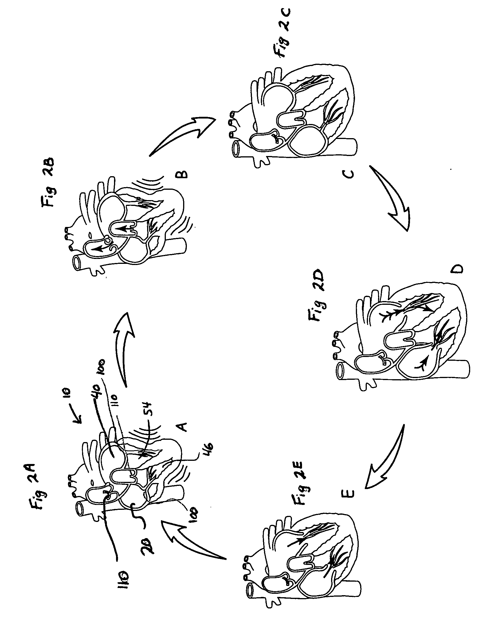
[0029] As blood is filling the RA 20, the LA 40 is simila...


PUM


Abstract

An implantable medical device provides ventricular pacing capabilities and optimizes AV intervals for multiple purposes. In general, intrinsic conduction is promoted by determining when electromechanical systole (EMS) ends and setting an AV interval accordingly. EMS is determined utilizing various data including QT interval, sensor input, and algorithmic calculations.

Description

BACKGROUND [0001] 1. Field of the Invention [0002] The present invention relates to implantable medical devices. More specifically, the present invention relates to implantable medical devices that are capable of delivering pacing stimuli. [0003] 2. Description of the Related Art [0004] At a superficial level, the mechanical aspects of the cardiac cycle of the human heart are fundamentally simple. The heart has four chambers. Deoxygenated blood is returned from the body to the right atrium. The right atrium (RA) fills the right ventricle (RV), which, upon contraction, pumps blood to the lungs. Oxygenated blood from the lungs fills the left atrium (LA), which in turn fills the left ventricle (LV). The contraction of the left ventricle then delivers oxygenated blood throughout the body. Thus, the atrial chambers serve the purpose of filling their respective ventricular chambers. [0005] Similarly, the electrical and timing aspects of the cardiac cycle are also fundamentally simple, at ...

Claims


Application Information

Patent Timeline
26 Apr 2007
Publication
US20070093874A1
IPC
A61N1/365
CPC
A61N1/368; A61N1/3682
Inventors
CHIRIFE, RAUL; COMBS, WILLIAM J.