Multi-level cache architecture having a selective victim cache

a cache architecture and multi-level technology, applied in the field of digital data processing hardware, can solve the problems of high latency and low throughput of the device typically used for storing mass data, and achieve the effect of reducing the number of devices and reducing the latency of the device to access the data stored thereon

Inactive Publication Date: 2007-04-26
IBM CORP
View PDF6 Cites 163 Cited by
  • Summary
  • Abstract
  • Description
  • Claims
  • Application Information

AI Technical Summary

Benefits of technology

[0013] A computer system includes a main memory, at least one processor, and a cache memory having at least two levels. A lower level selective victim cache receives cache lines evicted from a higher level cache. A selection mechanism selects lines evicted from the higher level cache for storage in the selective victim cache at a lower level, only some of the evicted lines being selected for storage in the victim cache.

Problems solved by technology

The devices typically used for storing mass data (e.g., rotating magnetic hard disk drive storage units) require relatively long latency time to access data stored thereon.
If a processor were to access data directly from such a mass storage device every time it performed an operation, it would spend nearly all of its time waiting for the storage device to return the data, and its throughput would be very low indeed.
Memory access requires a relatively large number of processor cycles, during which the processor is generally idle.
However, since the capacity of any of the cache levels is only a small fraction of the capacity of main memory, which is itself only a small fraction of the capacity of the mass storage unit(s), it is not possible to simply load all the data into the cache.
Therefore, conventional victim caches are often an inefficient technique for selective data to be stored in cache, and it can be questioned whether the hardware allocated to the victim cache is not better applied to increasing the size of other caches.
Although conventional techniques for designing cache hierarchies and selecting the cache contents have achieved limited success, it has been observed that in many environments, the processor spends the bulk of its time idling on cache misses.

Method used


Image

  • Multi-level cache architecture having a selective victim cache
  • Multi-level cache architecture having a selective victim cache
  • Multi-level cache architecture having a selective victim cache

Examples


Embodiment Construction

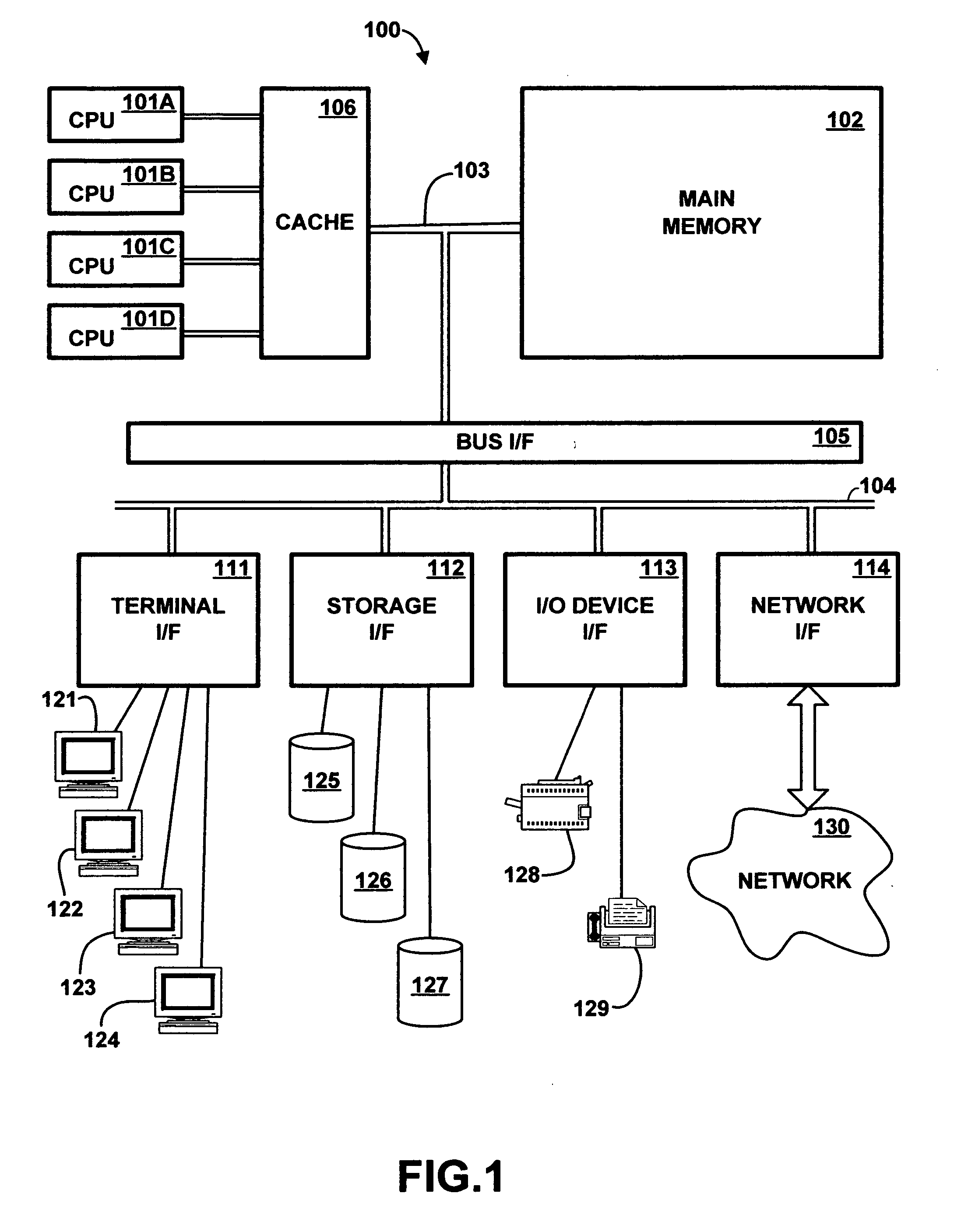
[0024] Referring to the Drawing, wherein like numbers denote like parts throughout the several views, FIG. 1 is a high-level representation of the major hardware components of a computer system 100 for utilizing a selective victim cache, according to the preferred embodiment of the present invention. The major components of computer system 100 include one or more central processing units (CPU) 101A-101D, main memory 102, cache memory 106, terminal interface 111, storage interface 112, I / O device interface 113, and communications / network interfaces 114, all of which are coupled for inter-component communication via buses 103, 104 and bus interface 105.

[0025] System 100 contains one or more general-purpose programmable central processing units (CPUs) 101A-101D, herein generically referred to as feature 101. In the preferred embodiment, system 100 contains multiple processors typical of a relatively large system; however, system 100 could alternatively be a single CPU system. Each pro...


PUM


Abstract

A computer system cache memory contains at least two levels. A lower level selective victim cache receives cache lines evicted from a higher level cache. A selection mechanism selects lines evicted from the higher level cache for storage in the victim cache, only some of the evicted lines being selected for the victim. Preferably, two priority bits associated with each cache line are used to select lines for the victim. The priority bits indicate whether the line has been re-referenced while in the higher level cache, and whether it has been reloaded after eviction from the higher level cache.

Description

FIELD OF THE INVENTION [0001] The present invention relates to digital data processing hardware, and in particular to the design and operation of cached memory and supporting hardware for processing units of a digital data processing device. BACKGROUND OF THE INVENTION [0002] In the latter half of the twentieth century, there began a phenomenon known as the information revolution. While the information revolution is a historical development broader in scope than any one event or machine, no single device has come to represent the information revolution more than the digital electronic computer. The development of computer systems has surely been a revolution. Each year, computer systems grow faster, store more data, and provide more applications to their users. [0003] A modern computer system typically comprises a central processing unit (CPU) and supporting hardware necessary to store, retrieve and transfer information, such as communications buses and memory. It also includes hard...

Claims


Application Information

Patent Timeline
Patent Type & Authority Applications(United States)
IPC IPC(8): G06F12/00
CPCG06F12/0897G06F12/126G06F12/128
Inventor VANDERWIEL, STEVEN PAUL
Owner IBM CORP
Why Eureka
Try Eureka