Nx steel lumber

a technology of c-shaped studs and elongated structures, applied in the direction of girders, joists, trusses, etc., can solve the problems of increased interest in fabricating and constructing buildings with frames, c-shaped studs that are susceptible to local buckling, bending, bending, bending, etc., to achieve the effect of increasing lateral resistance, increasing lateral resistance, and improving lateral resistan

Inactive Publication Date: 2007-05-03
KIM WHITTY SUK K
View PDF9 Cites 15 Cited by
  • Summary
  • Abstract
  • Description
  • Claims
  • Application Information

AI Technical Summary

Benefits of technology

[0020]FIG. 2 is a three dimensional partial side view of FIG. 1 illustrating the stiffening lips, the variable exaggerated bending and the angular intervening web extensions and parallel flanges by which there is improved lateral resistance.
[0021]FIG. 3 is a cross sectional view of two abutted C-shaped structural members of FIG. 1 along the outside web side as a composite truss vertical beam or a structural component that provides increased lateral resistance.
[0022]FIG. 4 is a cross sectional view of two C-shaped structural members of FIG. 1, facing in opposite directions, abutted along the outside of the parallel lip members as a composite truss vertical beam or a structural component for increased lateral resistance.
[0023]FIG. 5 is a cross sectional view of two C-shaped structural members of FIG. 1, facing in opposite directions with one member inserted and pressed into a second elongate member, forming a fully enclosed metal channel, as a composite truss vertical beam or a structural component for increased lateral resistance.

Problems solved by technology

Common C-shaped studs may be susceptible to local, torsional, flexural, torsional-flexural, lateral-torsional or distortional buckling.
The rising cost of lumber has caused increased interest in fabricating and constructing buildings with frames of sheet metal construction members.

Method used


Image

  • Nx steel lumber
  • Nx steel lumber
  • Nx steel lumber

Examples


Embodiment Construction

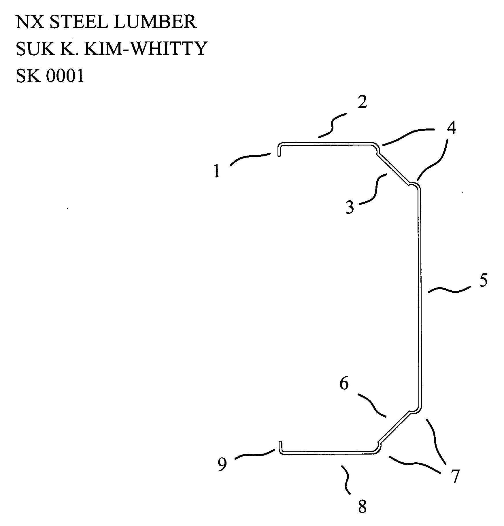
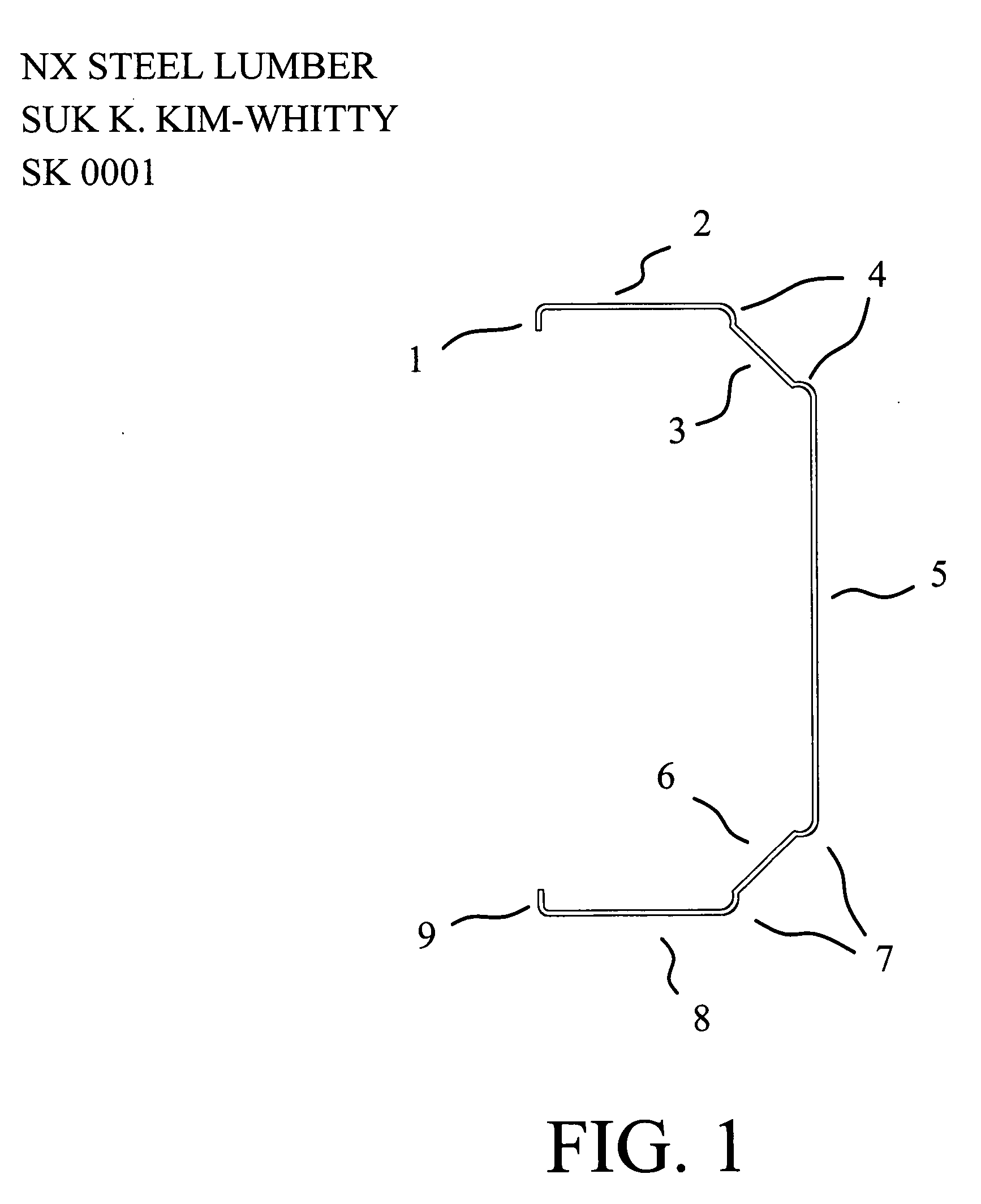
[0024] The structural member illustrated in FIG. 1 would be roll formed from thin, high tensile, galvanized steel in a structural grade. It can be roll formed by a single passage of an initially flat strip of sheet metal through a series of stands of forming rolls which successively modify the shape of the strip passing through the machines. FIG. 1 is a cross sectional view of a first embodiment of the C-shaped construction member. It comprises a longitudinal, elongate web member 5 having an angular intervening web extension 3 with variable exaggerated bends 4 and extending laterally to flange member 2 perpendicular to web member 5 and extending to an end wall member I of the flange member 2, in which the stiffening lip 1 is formed substantially parallel to web member 5 at the cross sectional end. The variable exaggerated bends 4, on both sides of flange member 3, satisfies safety requirements and provides improved lateral strength. The longitudinal, elongate web member 5, being the...


PUM


Abstract

The invention is a cold formed, steel metal C-shaped structural member having an elongated web member with novel opposing angular intervening web extensions with variable exaggerated bends and extending laterally to opposing perpendicular flange members and extending to opposing end stiffening lips parallel to the center web member at the cross sectional ends.

Description

CROSS-REFERENCE TO RELATED APPLICATIONS [0001] Not Applicable. STATEMENT REGARDING FEDERALLY SPONSORED RESEARCH OR DEVELOPMENT [0002] Not Applicable. REFERENCE TO SEQUENCE LISTING, A TABLE, OR A COMPUTER PROGRAM LISTING COMPACT DISK APPENDIX [0003] Not Applicable. BACKGROUND OF THE INVENTION [0004] 1. Field of the Invention [0005] The present invention relates to a novel C-shaped elongate structural member, having improved fastening and lateral strength characteristics, and in particular providing load bearing frames, as determined per application by professional engineers. This invention is concerned with a structural member that is cold formed from sheet metal wherein the rigidity of the frame as a whole results from the angular intervening web extensions, perpendicular flanges, variable exaggerated bends and stiffening lips of the member. Various metal framing systems have been developed to reduce the cost and labor in the construction of partition structures. [0006] 2. Descripti...

Claims


Application Information

Patent Timeline
Patent Type & Authority Applications(United States)
IPC IPC(8): E04C3/30
CPCE04C3/07E04C2003/0413E04C2003/0421E04C2003/043E04C2003/0434E04C2003/0452E04C2003/0465E04C2003/0473
Inventor KIM-WHITTY, SUK K.
Owner KIM WHITTY SUK K
Why Eureka
Try Eureka