H-shaped railroad tie, and mold for manufacturing same
A sleeper and railway technology, applied in the field of a railway sleeper and the manufacture of the railway sleeper, can solve the problems of train off-line, increase of lateral resistance and longitudinal resistance, threat to train operation safety, etc., to increase the longitudinal resistance of the track bed and the track bed Effects of lateral resistance, increase of longitudinal resistance and lateral resistance, and elimination of 3-point support phenomenon
- Summary
- Abstract
- Description
- Claims
- Application Information
AI Technical Summary
Problems solved by technology
Method used
Image
Examples
Embodiment 1
[0065] Embodiment 1 relates to the railway H-type crossties of the present invention.
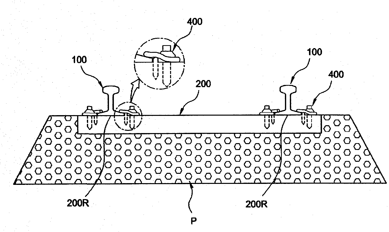
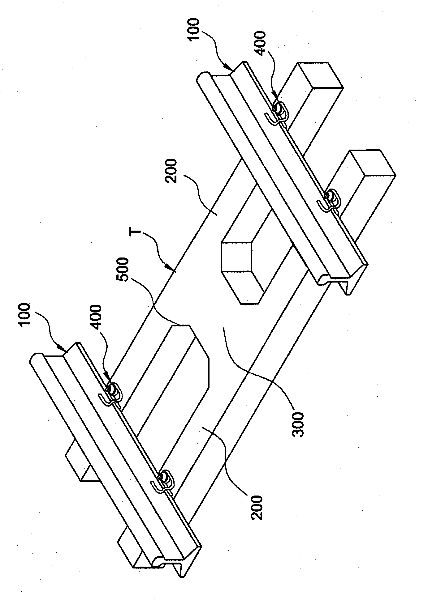
[0066] figure 1 It shows the installation drawing of the embodiment 1 where the rail is installed, figure 2 express figure 1 The up-and-down cross-sectional view of , image 3 Representing the perspective view of Embodiment 1, Figure 4 Represent the plan view of embodiment 1, Figure 5 express Figure 4 The AA' section diagram of Image 6 express Figure 4 The BB' cross-sectional view of Figure 7 express Figure 4 The CC' cross-section.
[0067] refer to figure 1 and figure 2 , The railway tie T of Embodiment 1 is set on the lower part of the rail 100 . The top surface of the railroad tie T is exposed, surrounded by ballast gravel P, and buried.
[0068] refer to image 3 , The railway tie T is formed to form an H shape. The railway tie T includes two inline main supports 200 and a ballast gravel resistance plate 300, and the two inline main supports 200 are separated fro...
Embodiment 2
[0083] Embodiment 2 relates to yet another railway H-type sleeper of the present invention.
[0084] Figure 8 Represents the plan view of embodiment 2, Figure 9 The setup diagram of Example 2 is shown.
[0085] refer to Figure 8 and Figure 9 , Embodiment 2 is the same as Embodiment 1, including two main supports 200 and a ballast gravel resistance plate 300 .
[0086] refer to Figure 8 and Figure 9 , any one of the two main supports 200 is protrudingly formed with a movement preventing protrusion 700 . The anti-movement protrusion 700 protrudes along the longitudinal direction of the rail 100 on the outer surface in the width direction of the main support 200 , and is formed so as to be located on the longitudinal extension of the ballast gravel resistance plate 300 . When the railroad tie T is installed, the anti-movement protrusion 700 contacts or connects with the main support 200 of the railroad tie T arranged adjacent to each other.
[0087] The anti-movement ...
PUM
 Abstract
Description
Claims
Application Information
 - R&D
- Intellectual Property
- Life Sciences
- Materials
- Tech Scout
- Unparalleled Data Quality
- Higher Quality Content
- 60% Fewer Hallucinations
Browse by: Latest US Patents, China's latest patents, Technical Efficacy Thesaurus, Application Domain, Technology Topic, Popular Technical Reports.
© 2025 PatSnap. All rights reserved.Legal|Privacy policy|Modern Slavery Act Transparency Statement|Sitemap|About US| Contact US: help@patsnap.com


