Auxiliary nose undercarriage, a force-transmission structure, and a rotary wing aircraft

Inactive Publication Date: 2007-05-03
EUROCOPTER
View PDF28 Cites 12 Cited by
  • Summary
  • Abstract
  • Description
  • Claims
  • Application Information

AI Technical Summary

Benefits of technology

[0113] a transparent surface improving visibility to the outside of the aircraft; and / or
[0115] In helicopters, transparent surfaces in the fairing of the fuselage are very useful for visibility towards the ground, in particular while landing.

Problems solved by technology

In the field of rotary wing aircraft, the term “shimmy” designates rapid oscillation of a wheel about a pivot axis leading to strong interfering forces that can even lead to the undercarriage being destroyed.
Firstly, this is often incompatible with the occupants of the aircraft having good visibility between the passenger compartment and the cockpit.
However, in the past, the structures of fuselages and undercarriages have not enabled the desired results to be achieved.
At least, at present, complying with certain specifications is contradictory to achieving other functions, thus making it necessary to find compromises that are not always acceptable in practice.
That document does not provide for a box having solid walls to be interposed at a distance from the side walls of the fuselage, above the auxiliary nose landing gear which itself disposed close to the center of the aircraft in its transverse direction.
The teaching of those documents in particular does not make it possible to obtain a nose landing gear and / or a structure for the fuselage of a rotary wing aircraft for ensuring the following features simultaneously: low ground clearance; good safety in the event of a crash; minimum aerodynamic resistance and instability; landing gear that is unaffected by the instability phenomenon known as “shimmy”; landing gear that is compatible with naval requirements; a structure of an arrangement that does not interfere with radars or other detectors; the occupants have good visibility towards the front; it is easy for occupants to move about in the aircraft; and inside spaces are made available.

Method used


Image

  • Auxiliary nose undercarriage, a force-transmission structure, and a rotary wing aircraft
  • Auxiliary nose undercarriage, a force-transmission structure, and a rotary wing aircraft
  • Auxiliary nose undercarriage, a force-transmission structure, and a rotary wing aircraft

Examples


Embodiment Construction

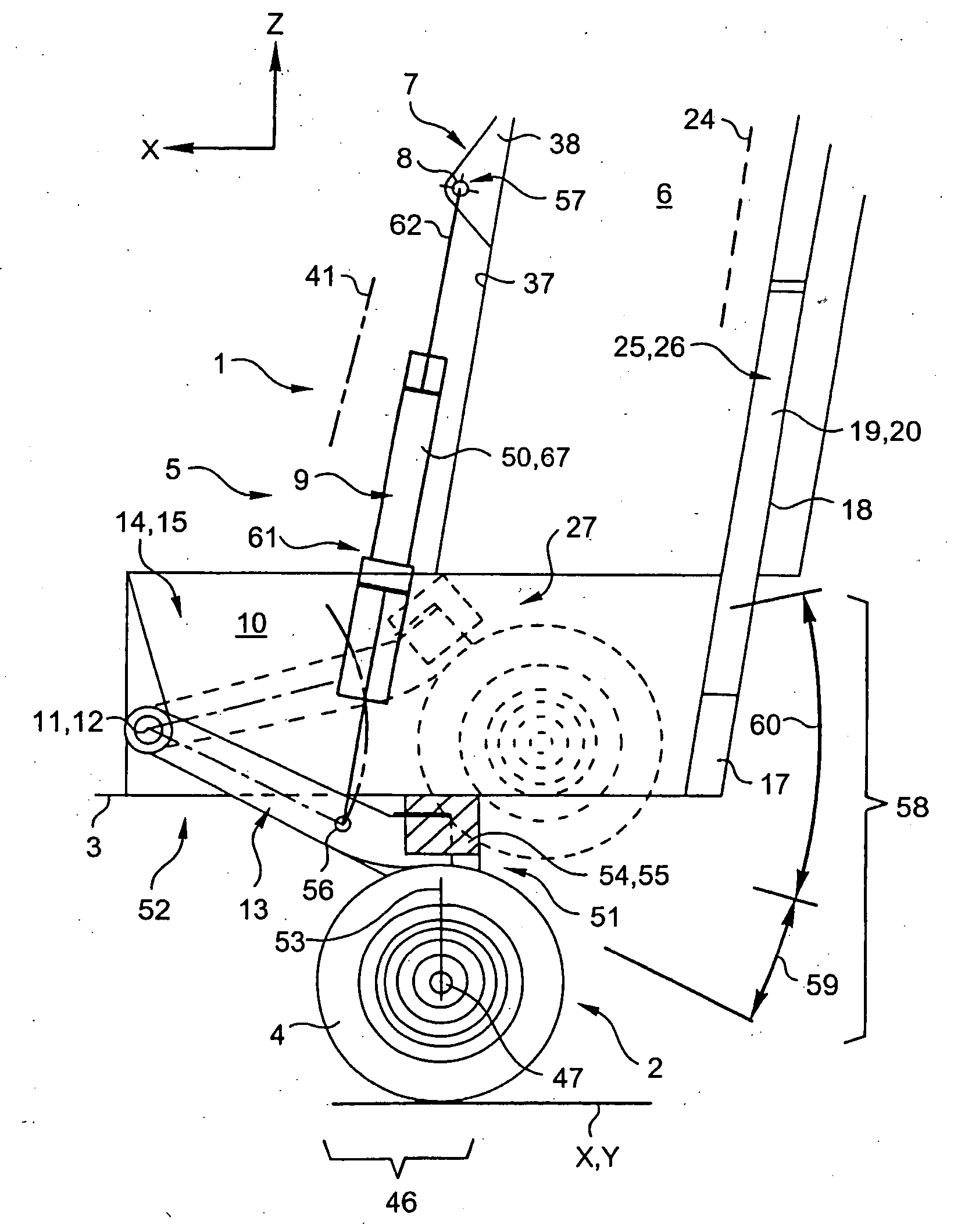
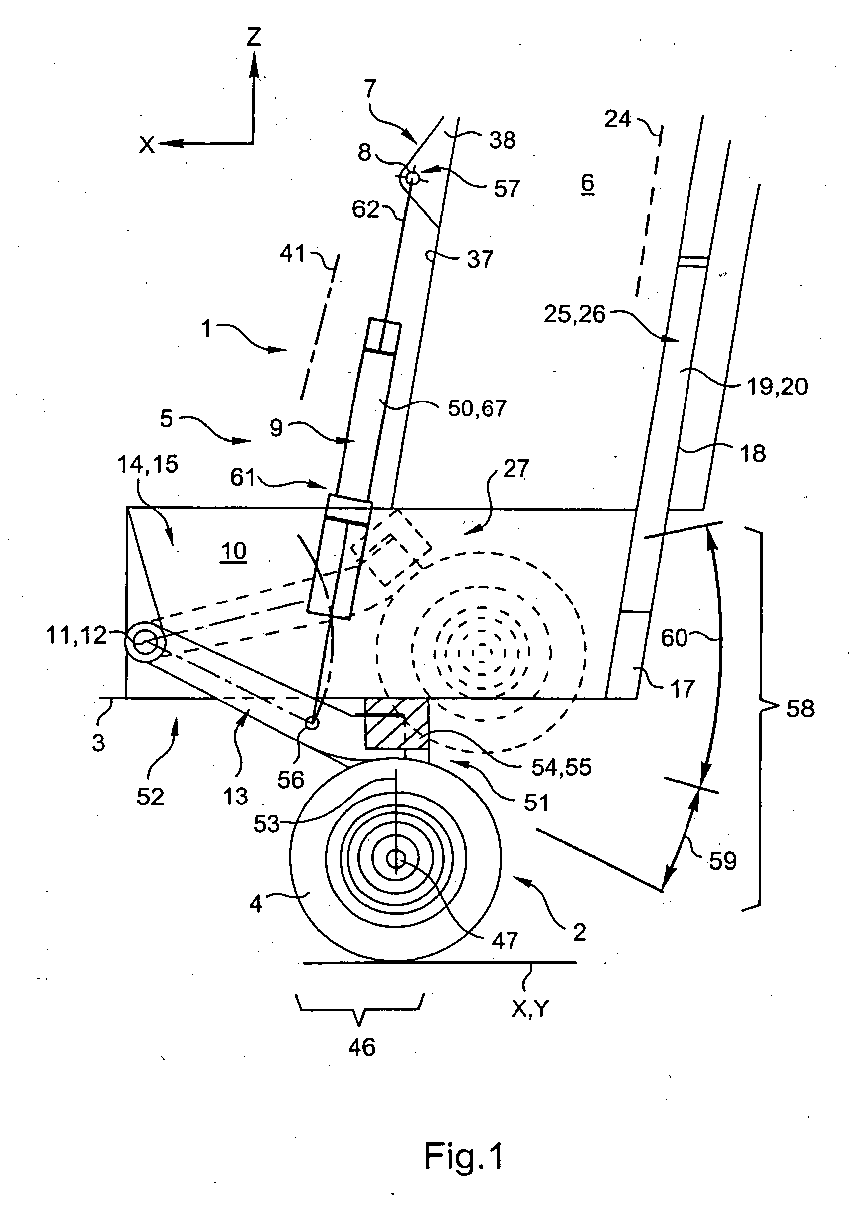
[0126] In the various figures, elements that are similar are designated by the same reference numerals.

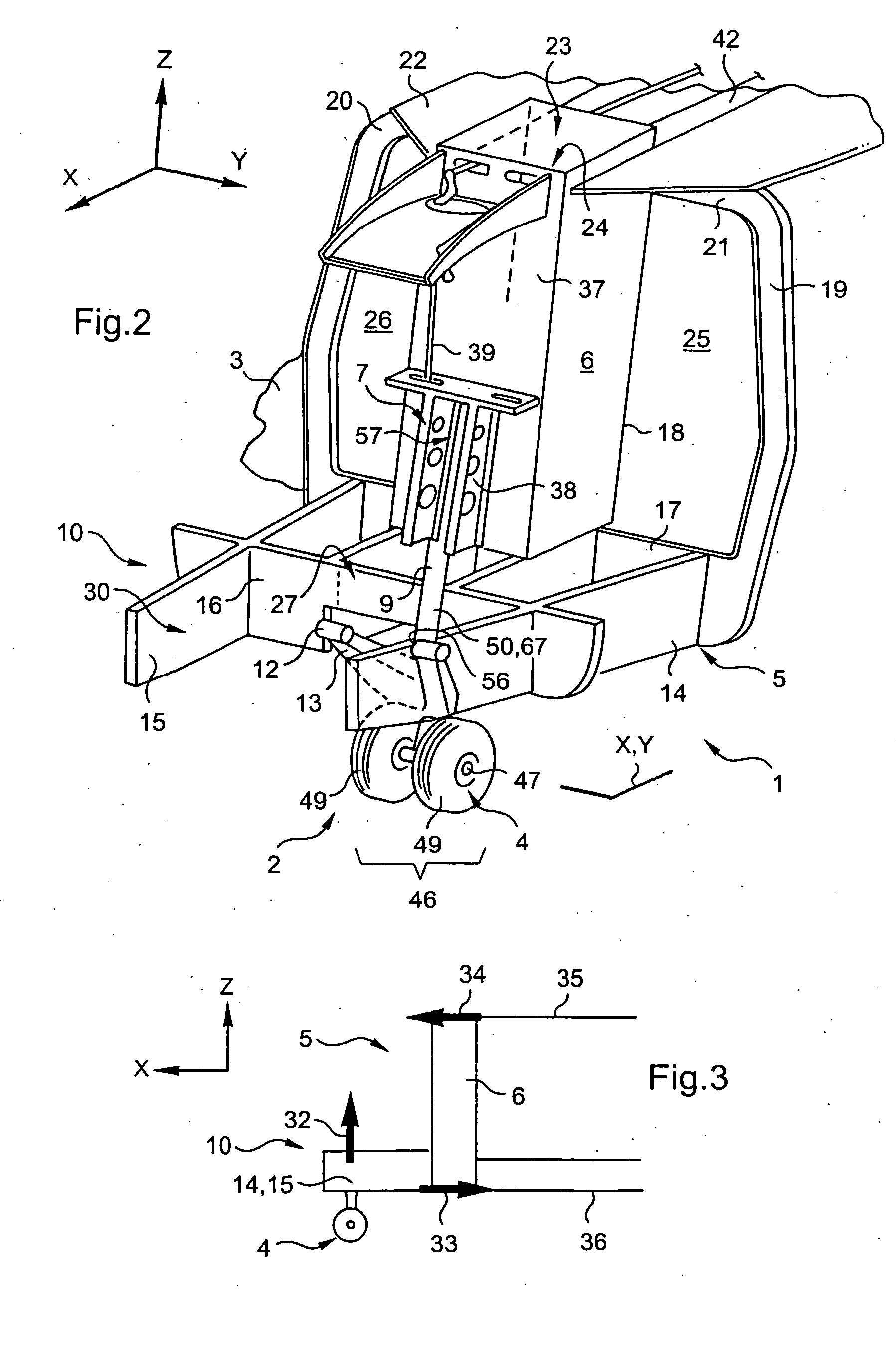
[0127] The figures show three mutually orthogonal directions, X, Y, and Z.

[0128] X designates a longitudinal direction corresponding to the main lengths or dimensions of the structures described.

[0129] Y corresponds to a transverse direction, corresponding to the lateral dimensions or widths of the structures described; these longitudinal and transverse directions X and Y are sometimes said to be the horizontal directions, for simplification purposes.

[0130] Z designates a third or “elevation” direction corresponding to the height dimensions of the structures described: the terms high / low are relative thereto; for simplification purposes, this Z direction is sometimes said to be vertical.

[0131] Together the directions X and Y define an X, Y plane referred to as a “main” plane (perpendicular to the plane of the sheet of FIG. 1) within which there is inscribed the polygon of supp...


PUM


Abstract

A steerable auxiliary nose undercarriage (2) for a rotary wing aircraft (1); the undercarriage (2) being retractable substantially rearwards. In the undercarriage (2), an oscillating system (13) presents a elevation stroke (58) about its hinged front end (52) that is greater than a shock absorbing stroke (59), and a shock-absorbing actuator (9) possesses retraction elements for going beyond a high abutment position of the oscillating system (13) so that the oscillating system (13) and the shock-absorbing actuator (9) provide both a shock-absorption function and an undercarriage retraction function.

Description

[0001] The invention relates to a nose undercarriage for a rotary wing aircraft such as a rotorcraft. The invention also relates to a force-transmission structure provided with such an undercarriage, and it also relates to an aircraft. BACKGROUND OF THE INVENTION [0002] In numerous such aircraft, in particular for the purpose of ensuring that the aircraft can be used for multiple purposes in spite of the constraints set out below, the following are guaranteed: [0003] ground clearance should be reduced as much as possible; [0004] safety should be acceptable in the event of an emergency or crash landing; [0005] aerodynamic resistance should be low; and [0006] the aircraft should have excellent stability on the ground. [0007] These constraints lead in particular to providing landing gear mounted on the aircraft so as to be retractable, with the landing gear also operating in a specific manner in the event of an emergency, and in particular of a crash. [0008] Furthermore, in certain air...

Claims


Application Information

Patent Timeline
IPC IPC(8): B64C25/10
CPCB64C25/00B64C25/04B64C25/14B64C25/10B64C27/04B64C25/08
Inventor BIETENHADER, CLAUDE
Owner EUROCOPTER
Why Eureka
Try Eureka