Drive unit

a technology of drive unit and drive shaft, which is applied in the direction of piezoelectric/electrostrictive/magnetostrictive devices, instruments, mountings, etc., can solve the problems of time and labor, variation in unit performance, and fragmentation of component parts, so as to reduce the variation in frictional force and drive performance, the effect of cost reduction

Inactive Publication Date: 2007-05-03
KONICA MINOLTA OPTO
View PDF9 Cites 20 Cited by
  • Summary
  • Abstract
  • Description
  • Claims
  • Application Information

AI Technical Summary

Benefits of technology

[0030] According to the drive unit of the present invention, since the press member is provided integrally with the movable member, for example, by insert molding, the assembling step for the press member can be omitted, allowing a cost reduction to be achieved, and moreover the press member is free from separation from the movable member due to a shock of fall.
[0031] Further, in the case where the press member is provided so as to abut directly on the drive friction member so that the sliding friction member is omitted, a further cost reduction can be achieved and moreover the assembly becomes easier to carry out. Still more, whereas expanding the press member by hand for assembling of the sliding friction member in the assembly process would cause the press member to be plastically deformed, making a factor of variations in frictional force and unit performance, the omission of the sliding friction member allows such events to be reduced.
[0032] Furthermore, in the case where the press member is formed so as to be twistable with respect to the axial direction of the drive friction member that is an axial member, even if the press member, when provided integrally with the movable member, has resulted into a skew more or less, generally uniform pressing force can be made to act on the drive friction member in the axial direction so that variations in the frictional force and the drive performance can be reduced.

Problems solved by technology

Thus, the assembly would involve time and labor.
In this case, there would arise variations in frictional force among individual units, lead also a cause of variations in unit performance.
Furthermore, there has also been a possibility that component parts might be decomposed and scattered upon a shock of fall.

Method used


Image

  • Drive unit
  • Drive unit
  • Drive unit

Examples


Embodiment Construction

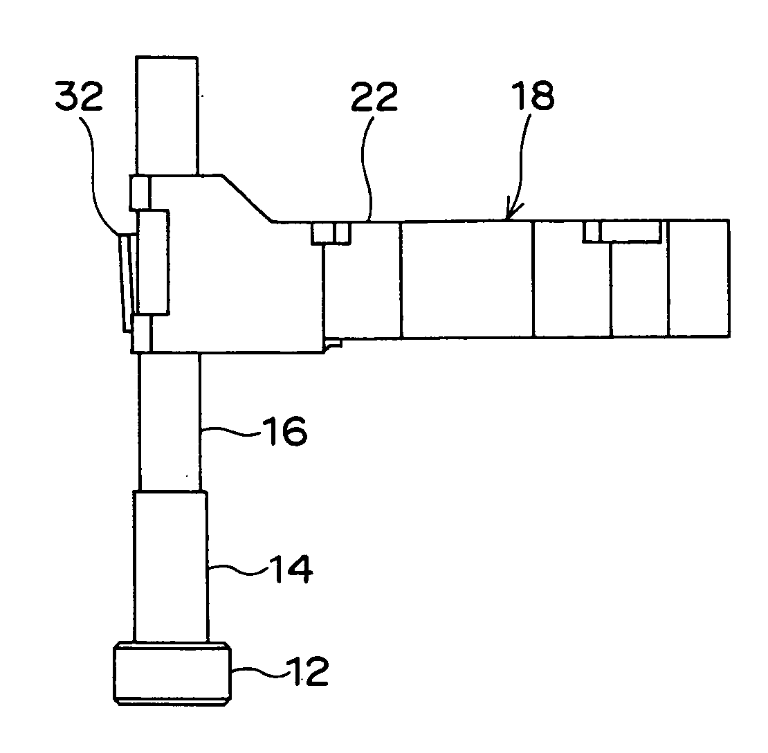
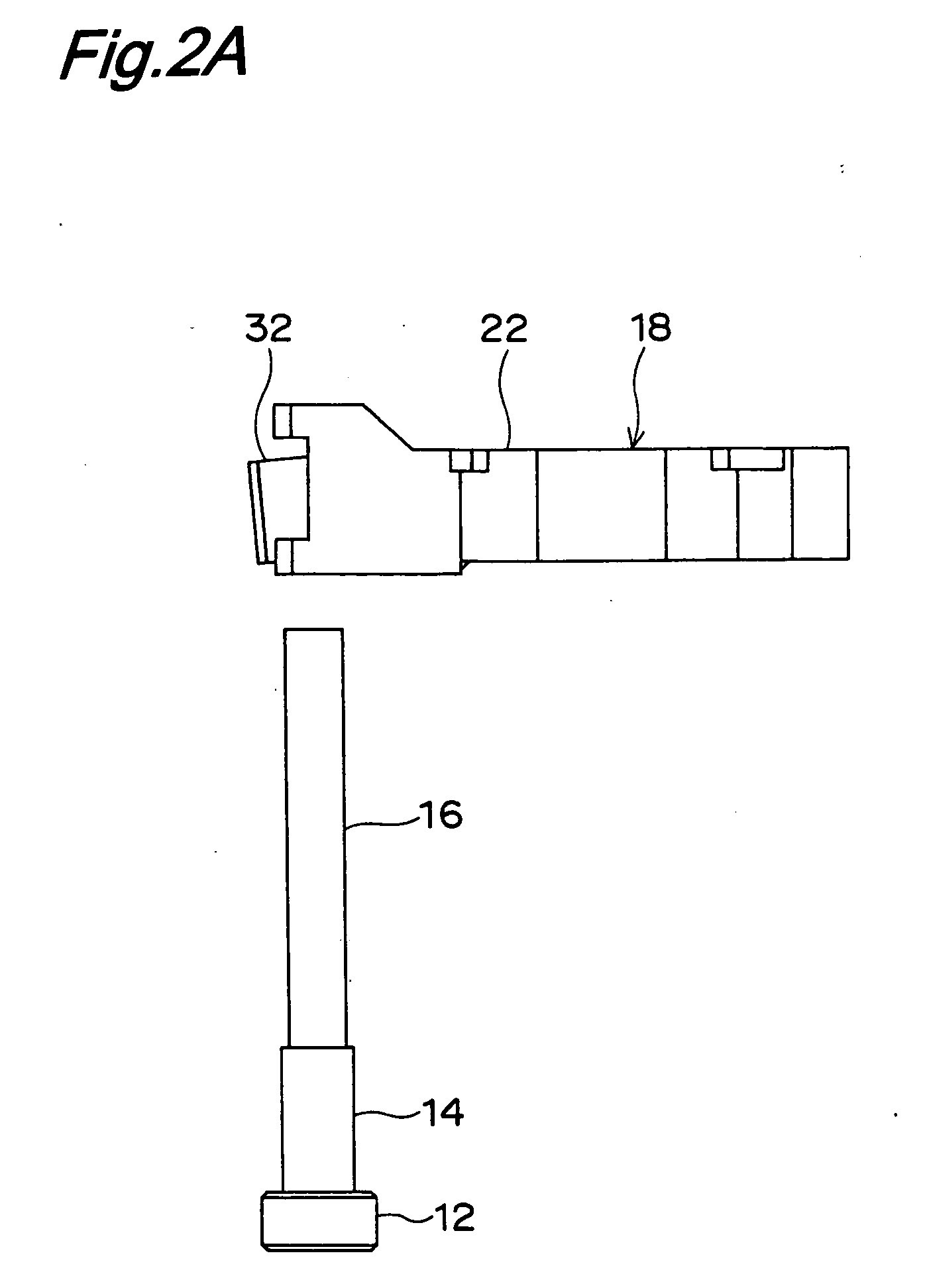
[0040]FIG. 1 is an exploded perspective view of a drive unit 10 which is an embodiment of the present invention, where an assembled state of the drive unit 10 is nearly identical to that shown in FIG. 6.

[0041] The drive unit 10 is composed of a cylindrical-shaped weight 12 to be fixed to an immovable part of a device into which the drive unit 10 is to be incorporated, a piezoelectric element (electromechanical conversion element) 64 which is cylindrical-shaped as an example and of which one end in its expansion / contraction direction is fixed to the weight 12, for example, by adhesion, a drive friction member 16 which is a cylindrical bar-shaped member as an example and which is to be fixed to the other end of the piezoelectric element 14 in its expansion / contraction direction, for example, by adhesion, and a movable member 18 which is to be fitted to the drive friction member 16 by frictional force. The cylindrical bar shape of the drive friction member 16 allows the drive friction...


PUM


Abstract

A drive unit of the present invention includes a piezoelectric element, a drive friction member fixed to one end of the piezoelectric element, and a movable member frictionally fitted to the drive friction member. By making the piezoelectric element expanded and contracted, the movable member is moved relative to the drive friction member. The leaf spring for pressing the movable member against the drive friction member is provided integrally with the movable member.

Description

RELATED APPLICATION [0001] This application is based on Japanese Patent Application No. 2005-318145, the content of which is incorporated herein by reference. BACKGROUND OF THE INVENTION [0002] The present invention relates to drive units, more particularly, to a drive unit which uses an electromechanical conversion element such as a piezoelectric element and which is suitably used for, for example, lens drive or precision stage drive. [0003] Conventionally, there has been known such a drive unit 60 as shown in FIG. 6. This drive unit 60 is composed of a cylindrical-shaped weight 62 to be fixed to an immovable part of a device into which the drive unit 60 is to be incorporated, a piezoelectric element (electromechanical conversion element) 64 which is cylindrical-shaped as an example and of which one end in its expansion / contraction direction is fixed to the weight 62, for example, by adhesion, a drive friction member 66 which is a cylindrical bar-shaped member as an example and whi...

Claims


Application Information

Patent Timeline
Patent Type & Authority Applications(United States)
IPC IPC(8): H02N2/00
CPCG02B7/08H02N2/025H02N2/02
Inventor SUEYOSHI, HIROHISASOUGAWA, TADATOMI
Owner KONICA MINOLTA OPTO
Why Eureka
Try Eureka