
Knee prosthesis

a knee joint and prosthesis technology, applied in the field of knee joint prosthesis, can solve the problems of long-term tka failure, unpredictable cancellous bone ingrowth in the tibial prosthesis, pain in the knee joint, etc., and achieve the effect of promoting bone ingrowth

Inactive Publication Date: 2007-05-03
UNIVERSITY OF VERMONT
View PDF19 Cites 27 Cited by
  • Summary
  • Abstract
  • Description
  • Claims
  • Application Information

AI Technical Summary

Benefits of technology

[0016] In one aspect, the invention provides, a knee replacement prosthesis comprising a patellar component comprising a substantially cir

Problems solved by technology

Arthritis of the knee joint is not only painful but can be permanently debilitating.
Loosening due to micromotion of the tibial component is the most frequent cause of long term TKA failure.
However, cancellous bone ingrowth in the tibial prosthesis has been unpredictable.
Yet, even bone cement fixated prosthetic components are susceptible to loosening.
The Shaw prosthesis suffers from disadvantages primarily resulting from the placement of the porous bone ingrowth material on the central stem and pegs.
While this design would appear to effectively promote bone ingrowth, because bone ingrowth occurs about the central stem and pegs, removal of the tibial prosthesis (as a result of infection) would cause excessive tibia damage.
Moreover, the bone ingrowth area is of limited surface area and does not effectively utilize the larger surface area of the upper end of the tibia for bone ingrowth.

Method used


Image

  • Knee prosthesis
  • Knee prosthesis
  • Knee prosthesis

Examples


example 1

[0095] A uniform density polyurethane foam was used as a substrate for this study, Last-A-Foam (Pacific Plastics Research Laboratories, Vashon Island, Wash.). Its material properties are similar to tibial cancellous bone, and its use is well documented. The foam was machined into uniform blocks and each block was fitted to a testing jib to prevent variability between testing sequences and eliminate background motion artifact.

[0096] The testing jig consisted of liquid mercury strain gauges (LMSG, Parks Medical Electronics, Beaverton, Oreg.) attached to translatable arms (X, Y, Z) for alignment with the tibial tray. Each LMSG was attached to a translatable arm and attached to the tibial tray. Four LMSGs were used per tray fixed to the anterior, posterior, medial, and lateral regions of the tray. The LMSG records a voltage change due to movement of the tray. Calibration curves for each LMSG allow extrapolation of the movement in micrometers. Calibration curves were obtained by opening...

example 2

[0110] A uniform density polyurethane foam is used as a substrate for this study, Last-A-Foam (Pacific Plastics Research Laboratories, Vashon Island, Ish.). Its material properties are similar to femoral cancellous bone, and its use is well documented. The foam is machined into uniform blocks and each block is fitted to a testing jib to prevent variability between testing sequences and eliminate background motion artifact.

[0111] The testing jig consisted of liquid mercury strain gauges (LMSG, Parks Medical Electronics, Beaverton, Oreg.) attached to translatable arms (X, Y, Z) for alignment with the femoral component. Each LMSG is attached to a translatable arm and attached to the femoral component. Four LMSGs are used per component fixed to the anterior, posterior, medial, and lateral regions of the component. The LMSG records a voltage change due to movement of the component. Calibration curves for each LMSG allow extrapolation of the movement in micrometers. Calibration curves ar...


PUM

PropertyMeasurementUnit
Thicknessaaaaaaaaaa
Widthaaaaaaaaaa
Widthaaaaaaaaaa

Abstract

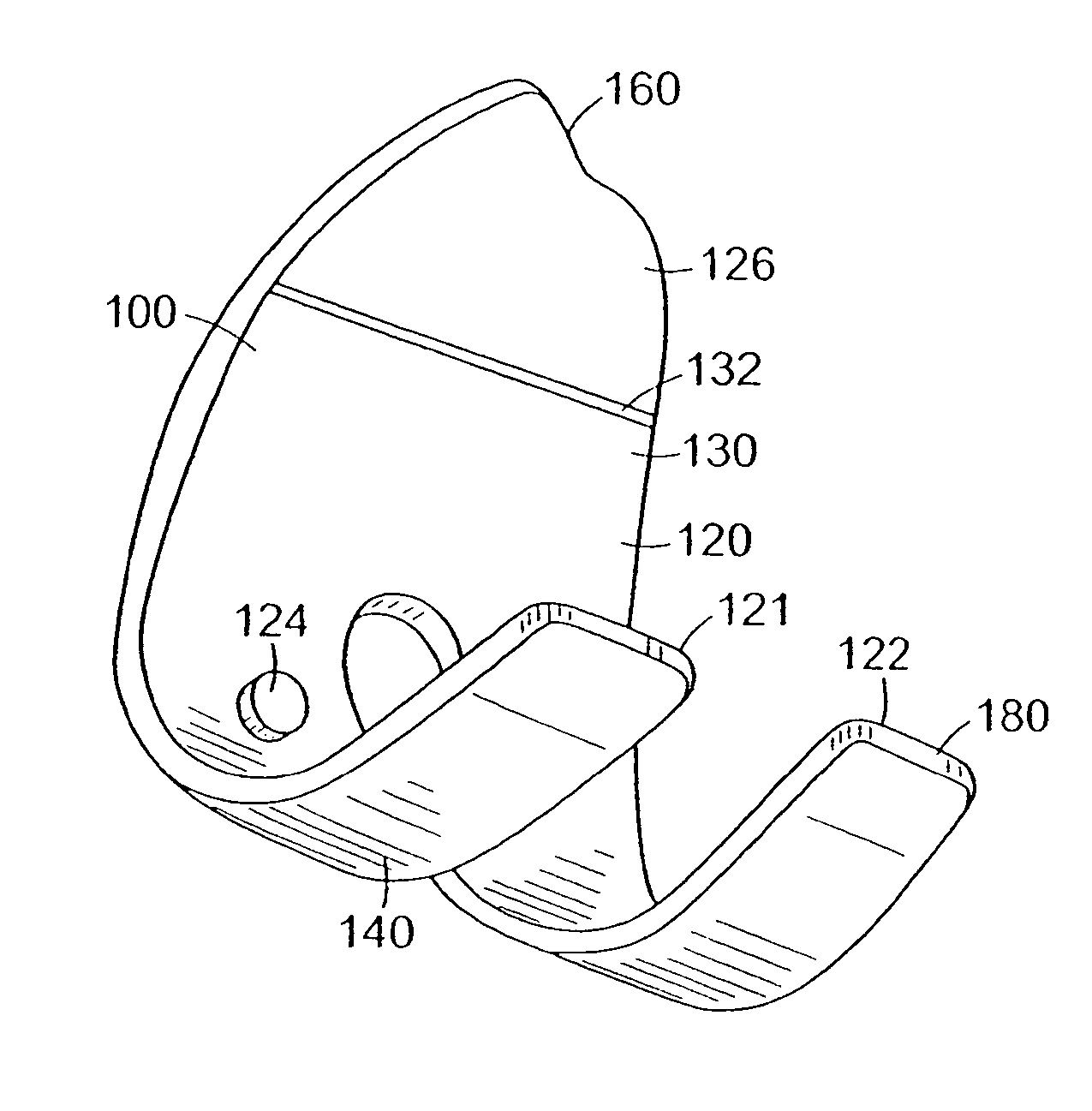
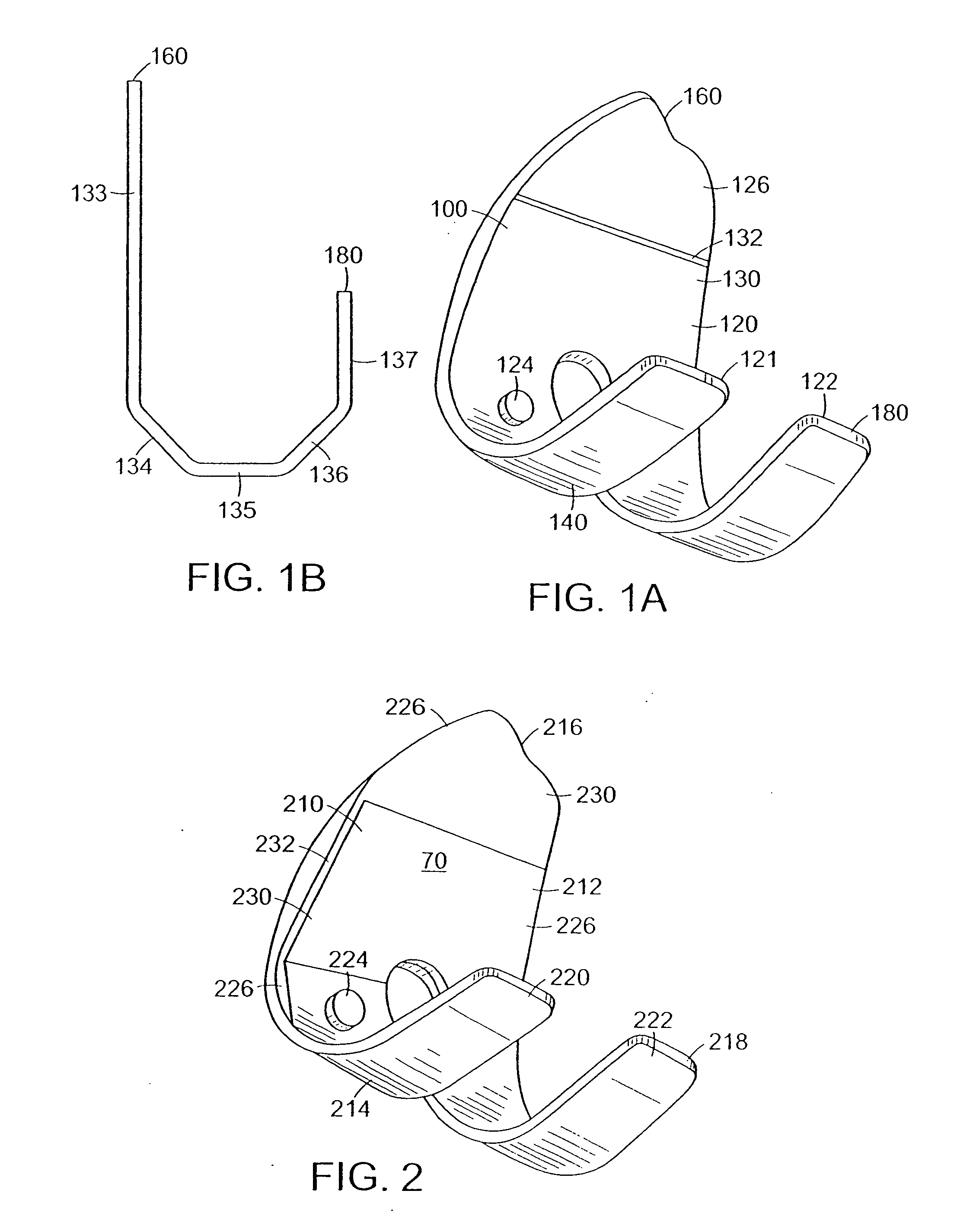
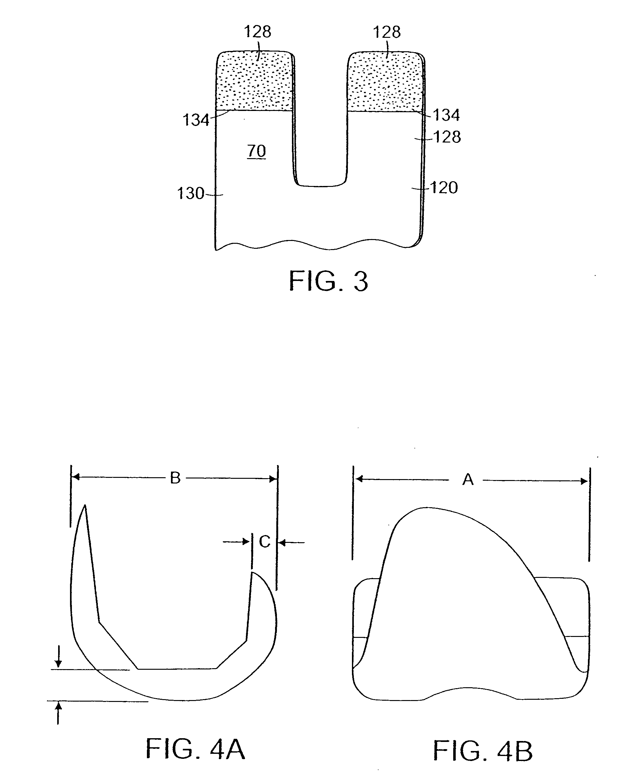
The invention relates to an orthopedic prosthetic device and a method of implanting such device. More particularly, the invention relates to a knee replacement prosthesis having femoral, patellar, and tibial components having surfaces for receiving bone cement and surfaces which promotes bone ingrowth.

Description

RELATED APPLICATIONS [0001] This application claims priority to U.S. Provisional Application Ser. No. 60 / 670,813, filed Apr. 12, 2005.BACKGROUND OF THE INVENTION [0002] Arthritis of the knee joint is not only painful but can be permanently debilitating. With ever increasing frequency, doctors are replacing arthritic knees with prosthetic devices having a tibia component, a femur component and a patella component which mimic the articulation between the tibia and the femur. A complete knee replacement is often referred to as a Total Knee Arthroplasty (TKA). It is a primary goal of TKA to provide a stable, pain free and long lasting knee replacement. [0003] Fixation of the tibia, femur and patella components of a prothesis during implantation has customarily involved either bone cement or natural bone ingrowth. Orthopedic surgeons typically prefer cementless fixation for what is considered to be its potential to provide long term implant stability. Knee replacement prothesis wherein f...

Claims


Application Information

Patent Timeline
IPC IPC(8): A61F2/38
CPCA61F2/30767A61F2/38A61F2/3859A61F2/3877A61F2/389A61F2002/30004A61F2002/30769A61F2002/30909A61F2002/3093A61F2250/0014A61F2310/00017A61F2310/00023A61F2310/00029A61F2310/00059A61F2310/00089A61F2310/00095A61F2310/00179A61F2310/00203A61F2310/00239A61F2310/00353A61F2310/00592A61F2310/00796A61F2310/0097
Inventor INCAVO, STEPHENBEYNNON, BRUCE D.
Owner UNIVERSITY OF VERMONT
Learn More