Apparatus and method for controlling camera of robot cleaner

a robot cleaner and camera technology, applied in the field of apparatus and a method for controlling the camera mounted at the robot cleaner, can solve the problems of boosting the manufacturing cost of the robot cleaner and complicated construction of the robot cleaner

Active Publication Date: 2007-05-03
LG ELECTRONICS INC
View PDF12 Cites 22 Cited by
  • Summary
  • Abstract
  • Description
  • Claims
  • Application Information

AI Technical Summary

Benefits of technology

[0010] A further object of the present invention is to provide an apparatus and a method for controlling a camera of a robot cleaner, which may effectively travel the robot cleaner by repeating a photograph operation for sensing obstacles and confirming a position of the robot cleaner using one camera while the robot cleaner cleans a predetermined zone.

Problems solved by technology

That will make a construction of the robot cleaner complicated.
Further, a use of a plurality of camera modules boosts manufacturing cost of the robot cleaner.

Method used


Image

  • Apparatus and method for controlling camera of robot cleaner
  • Apparatus and method for controlling camera of robot cleaner
  • Apparatus and method for controlling camera of robot cleaner

Examples


embodiment 1

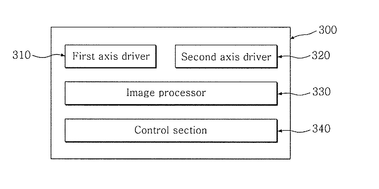
[0026]FIG. 3 is a block diagram showing a schematic construction of the robot cleaner according to an embodiment of the present invention.

[0027] A first axis driver 310 rotates and moves a camera in a first axis direction. A second axis driver 320 rotates and moves the same camera in a second axis direction.

[0028] An image processor 330 separately stores a first image photographed by the camera driven by the first axis driver 310 and a second image photographed by the camera driven by the second axis driver 320 in a memory (not shown). The image processor 330 reads the photographed images to sense a presence or absence and a pattern of obstacles and to detect a specific label for confirming a position of the robot cleaner.

[0029] As a power is applied to the robot cleaner, it operates. When the robot cleaner operates, a control section 340 positions the camera at an origin. Here, the origin is an initial position of the camera. The camera can drive from the origin to the first axi...

embodiment 2

[0045]FIG. 5 is a flow chart for illustrating a method for controlling a camera according to an embodiment of the present invention.

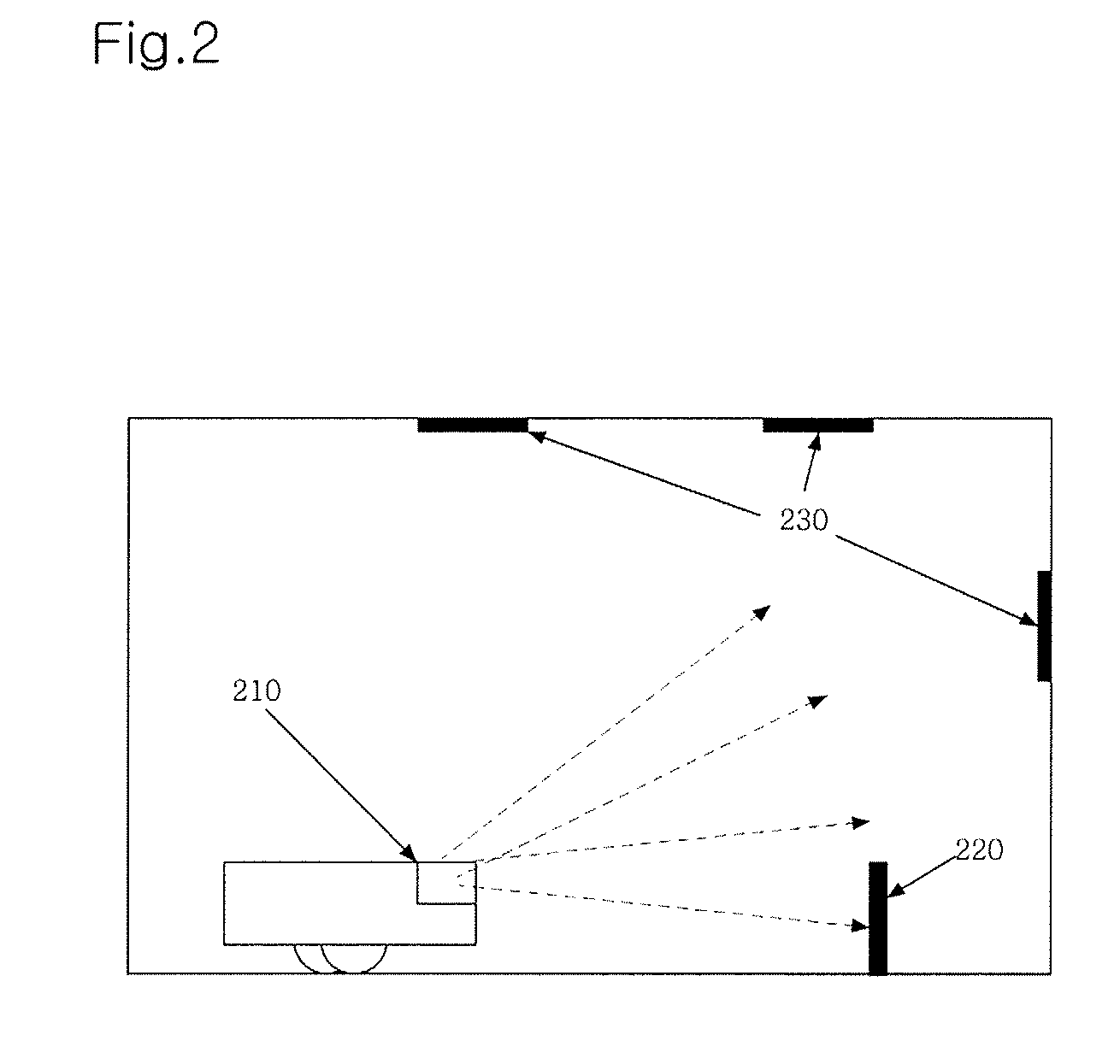
[0046] As shown in FIG. 5, when a power is applied to drive the robot cleaner, the control section 340 positions the camera at an origin (step S501). Here, the origin is an initial position of the camera. The camera can drive from the origin to the first axis direction or the second axis direction. Namely, the origin is positioned at an intersection of a first axis and a second axis. Once the camera is positioned at the origin, the control section 340 controls the first axis driver 310 or the second axis driver 320 at need during a traveling of the robot cleaner, so that it photographs front obstacles or a label installed at an upper side for compensating a position of the robot cleaner.

[0047] The label is marked as a predetermined pattern or character and is made of a shape to be easily attached at a position such as a ceiling or a wall in order to d...


PUM


Abstract

Disclosed are an apparatus and a method for controlling a camera mounted at a robot cleaner in order to sense obstacles and perform position compensation. The apparatus for controlling a camera of a robot cleaner includes a first axis driver for driving a camera mounted at the robot cleaner in a first axis direction; a second axis driver 320 for driving the camera in a second axis direction other than the first axis direction; an image processor 330 for receiving and processing an image photographed by the camera; and a control section 340 for controlling the first axis driver and the second axis driver, and controlling a traveling of the robot cleaner based on the image photographed by the camera.

Description

CROSS-REFERENCE TO RELATED APPLICATIONS [0001] This application claims benefit under 35 U.S.C. § 119 from Korean Patent Application No. 2005-0101804, filed on Oct. 27, 2005, the entire content of which is incorporated herein by reference. BACKGROUND OF THE INVENTION [0002] 1. Field of the Invention [0003] The present invention relates to an apparatus and a method for controlling a camera mounted at a robot cleaner in order to sense obstacles and perform a position compensation, and more particularly, to an apparatus and a method for controlling a camera of a robot cleaner, which photograph a subject to sense obstacles and to photograph a label for a position compensation by moving and controlling one camera mounted at a robot cleaner in two axis directions. [0004] 2. Description of the Related Art [0005] A conventional robot cleaner may sense cleaning zones or obstacles using a camera. Korean patent application No. 1998-23269 discloses a technique, which rotates a camera and a laser...

Claims


Application Information

Patent Timeline
Patent Type & Authority Applications(United States)
IPC IPC(8): G05B15/00
CPCA47L9/009G05D1/0246G05D2201/0203A47L2201/04A47L9/28A47L9/00A47L11/00
Inventor IM, HYOUNG-DEUKJUNG, IL-KYUN
Owner LG ELECTRONICS INC
Why Eureka
Try Eureka