
Device function restricting method and system in specific perimeters

Active Publication Date: 2007-05-03
SAMSUNG ELECTRONICS CO LTD
View PDF31 Cites 279 Cited by
  • Summary
  • Abstract
  • Description
  • Claims
  • Application Information

AI Technical Summary

Benefits of technology

[0011] The present invention provides a device function restricting method and system for specific perimeters, and more particularly to a device function restricting method and system for specific perimeters for preventing a user from using a device in an illegal manner and facilitating information leakage, if the user carries a device having a camera function and a memory function with him or her in specific perimeters where security is required, by transmitting a credential and a security policy to the device through a perimeter restriction channel and thus restricting a part of the device functions based on the credential and the security policy.

Problems solved by technology

However, there are some places where the functions of such mobile devices should be restricted when such mobile devices are used.
First, there are restricted areas for information security where information leakage must be prevented, such as in government agencies, military agencies, business agencies, and the like, where the handling of sensitive resources such as documents, prototype, and the like may occur.
Second, there are restricted areas for moral purposes zoned for preventing the violation of others' privacy by use of certain features of a mobile device, such as photographing others in public shower facilities or for keeping individual activities such as enjoying shows in a concert hall or reading books in a library away from others' disturbance.
Third, there are radioactive substance restriction areas zoned for protecting sensing equipment of airplanes and the like from interference caused by electromagnetic fields emitted from a mobile device.
However, current technical limitations have a problem of hardly providing reliable blocking.
However, the removal activities of mobile devices from users can give rise to an additional physical problem.

Method used


Image

  • Device function restricting method and system in specific perimeters
  • Device function restricting method and system in specific perimeters
  • Device function restricting method and system in specific perimeters

Examples


Embodiment Construction

[0037] Hereinafter, description will be made in detail on certain exemplary embodiments of the present invention with reference to the accompanying drawings.

[0038] It is noted that like reference numerals are used as long as possible to denote like parts or elements even though shown in different drawings in assigning the reference numerals to constituent parts or elements of each drawing.

[0039] For better understanding of the present invention, detailed description on well-known structures or functions will be avoided if it is judged that concrete description on the structures or functions distracts the gist of the present invention.

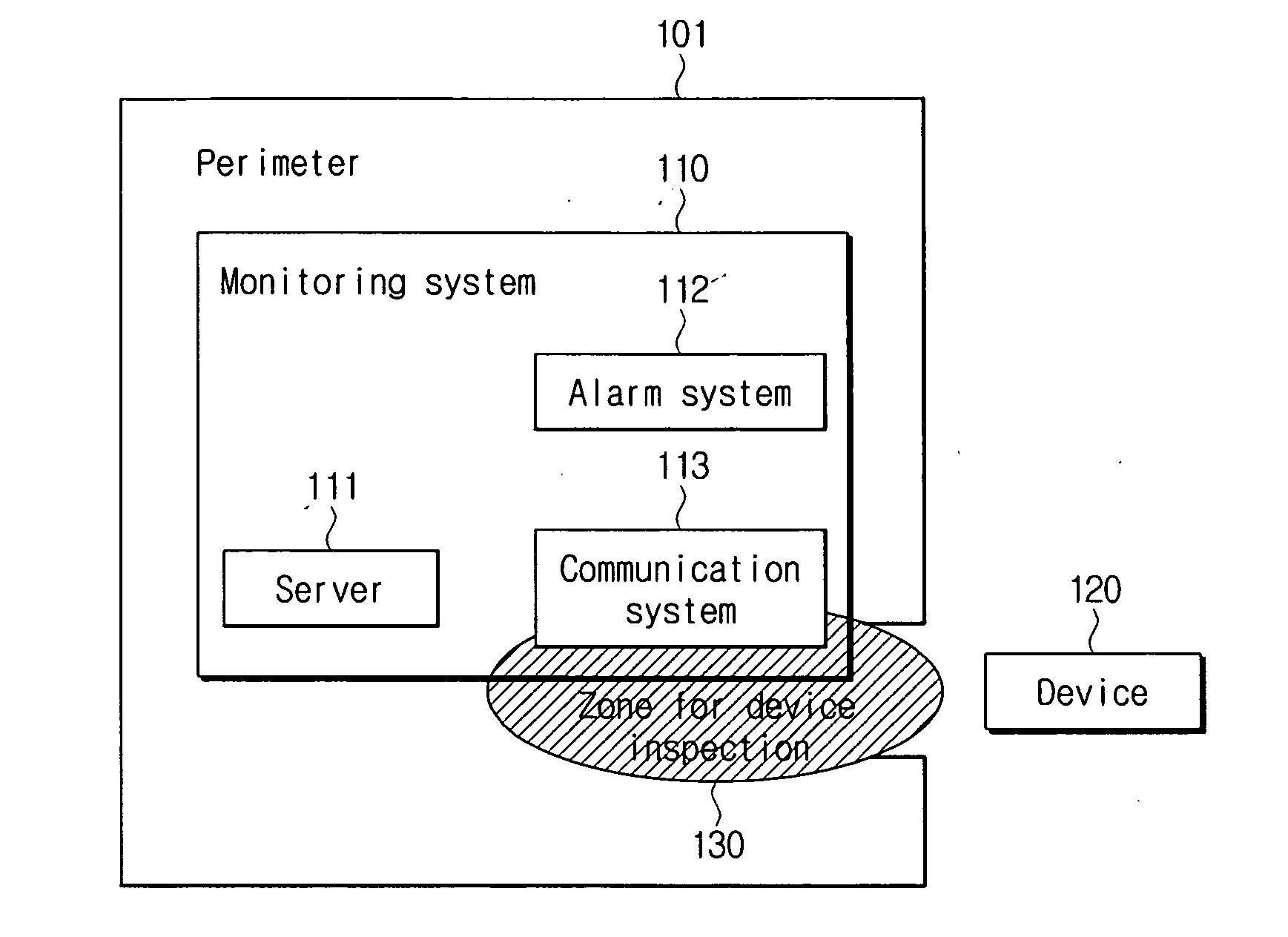
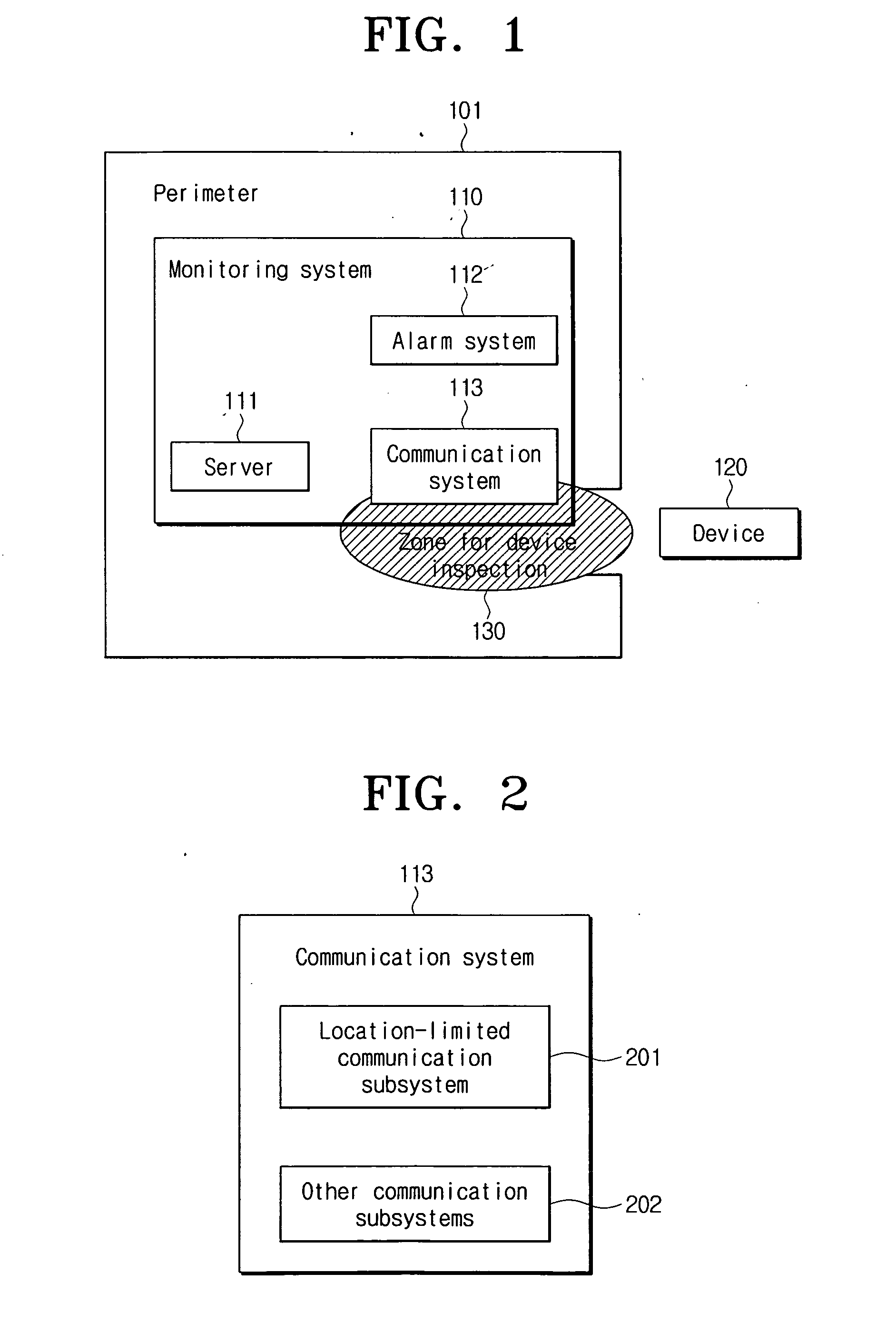
[0040]FIG. 1 is a view for schematically showing a configuration of a device function restricting system according to an exemplary embodiment of the present invention.

[0041] The device function restricting system according to the present invention includes a monitoring system 110 and a device 120.

[0042] The monitoring system 110 is located within a...


PUM


Abstract

An apparatus and method for restricting the functions of a device are provided. A restriction monitoring system includes a communication system that provides a location-limited communication channel that detects whether a device entering a perimeter is in an area for device inspection, a server that provides a credential and a security policy to the device and receives a report on whether the device violates the security policy through the location-limited communication channel, and an alarm system which triggers a security alarm when the device violates the security policy.

Description

CROSS-REFERENCE OF RELATED APPLICATIONS [0001] This application claims priority from Korean Patent Application No. 10-2005-0101778 filed on Oct. 27, 2005, the entire contents of which are incorporated herein by reference. BACKGROUND OF THE INVENTION [0002] 1. Field of the Invention [0003] Methods and apparatuses consistent with the present invention relate to device function restricting methods and systems in specific perimeters. More particularly, the present invention relates to a device function restricting method and system in specific perimeters for preventing a user from unauthorized use of a device and information leakage, such as, if the user carries a device having a camera function and a memory function in specific perimeters where security is required, the system transmits a credential and a security policy to the device through a perimeter restriction channel and thus restricts a portion of the device functions based on the credential and the security policy. [0004] 2. D...

Claims


Application Information

Patent Timeline
IPC IPC(8): H04L9/00H04L9/32G06F12/14G06F11/00G06F15/173G06F17/00G06K9/00G06F11/30G06F12/16H04K1/00G06F17/30G06F15/16G06F15/18G06F7/04G08B23/00G06F7/58G06K19/00
CPCG06F21/554G06F21/6209G06F2221/2101G06F2221/2103G06F2221/2111G06F2221/2149H04L63/102H04L12/22
Inventor LEE, KYUNG-HEEKORKISHKO, TYMUR
Owner SAMSUNG ELECTRONICS CO LTD
Learn More