Automotive seat air-conditioning system

a seat air conditioner and automobil technology, applied in the field of automobil seat air-conditioning system, can solve the problems of low energy efficiency of the vehicle as a whole, imposing a great burden on the power supply capacity of the vehicle, etc., and achieve the effect of reducing the size of the heat exchanger, facilitating the use of internal space of the vehicle seat, and improving comfort for the occupants

Inactive Publication Date: 2007-05-10
DENSO CORP
View PDF6 Cites 59 Cited by
  • Summary
  • Abstract
  • Description
  • Claims
  • Application Information

AI Technical Summary

Benefits of technology

[0013] In this aspect of the invention, the air-conditioning air, after being further controlled in temperature by the heat exchanger, is blown out from the surface of the vehicle seat, and therefore the comfort of the occupant is further improved. Especially, the cool-down operation has an immediate effect on the occupant.
[0014] According to this invention, there is provided an automotive seat air-conditioning system, wherein the heat exchanger is configured of a Peltier module (29). In this aspect of the invention, the heat exchanger can be reduced in size, and the internal space of the vehicle seat can be effectively utilized. Also, the cooling operation can be performed only by supplying electric power, while at the same time reducing the blowout noise level.
[0015] According to this inve

Problems solved by technology

In the case where a large capacity is required, on the other hand, a considerable amount of power must be supplied, often imposing a great burden on the power supply capacity of the vehic

Method used


Image

  • Automotive seat air-conditioning system
  • Automotive seat air-conditioning system
  • Automotive seat air-conditioning system

Examples


first embodiment

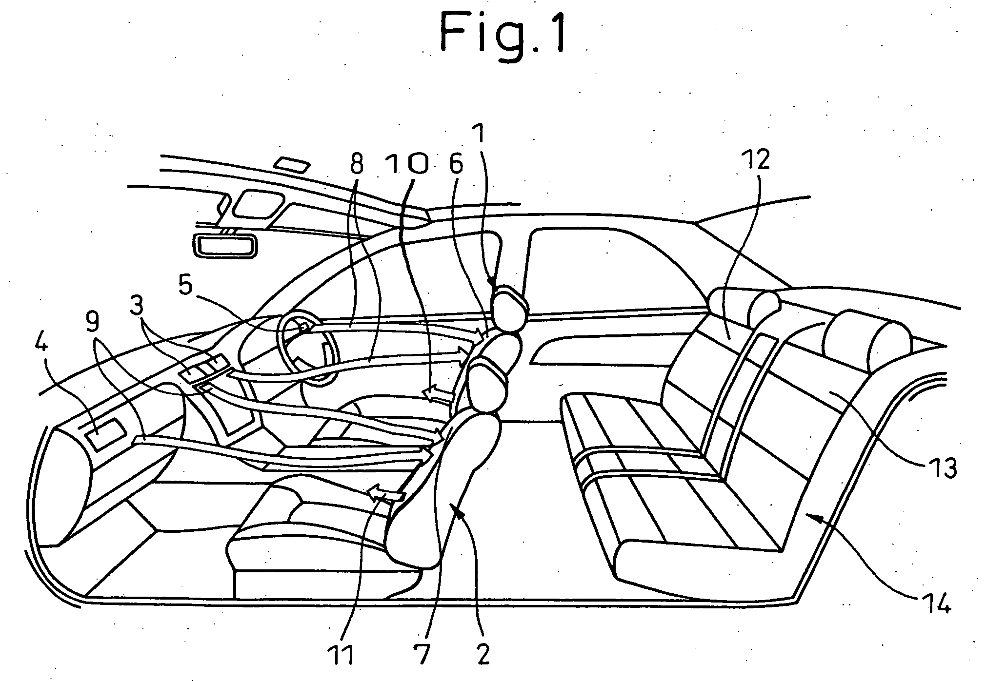
[0025] A first embodiment of the invention is explained below with reference to FIGS. 1 to 6. FIG. 1 is a schematic diagram showing the air flow for sucking in the air-conditioning air using an automotive seat air-conditioning system according to this embodiment. FIG. 6 is a diagram for explaining the operating conditions of the Peltier module of the automotive seat air-conditioning system and the automotive climate control system operatively interlocked with each other.

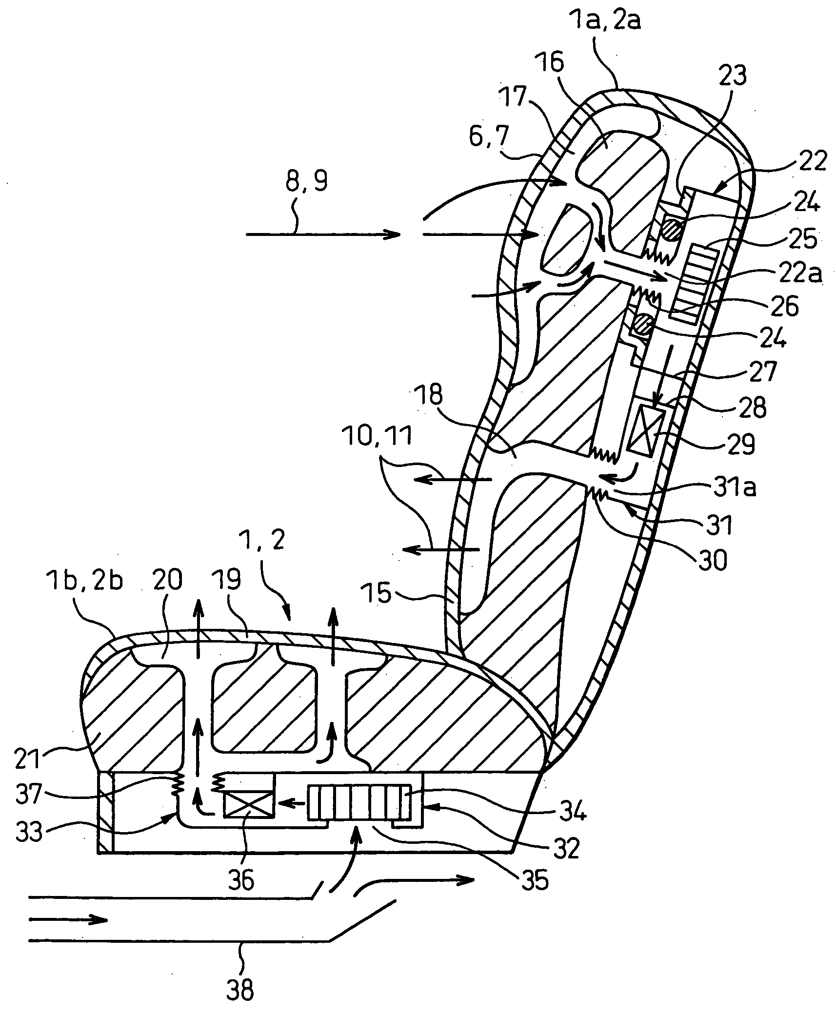
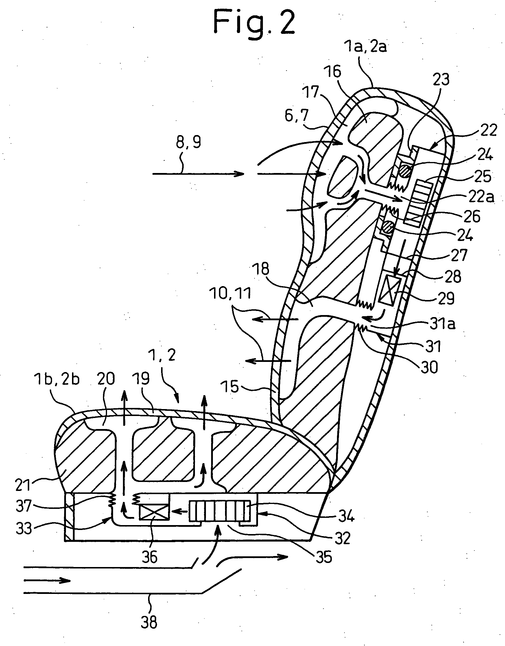
[0026] As shown in FIG. 1, the automotive seat air-conditioning system according to this embodiment comprises an automotive seat 1 including a seat portion 1b used an occupant and a seatback 1a against which the back of the occupant to leans and a blower 22 constituting a blowing means for sucking in the air-conditioning air 8 flowing in the compartments, wherein the air-conditioning air 8 is sucked in by the blower 22 from an air inlet 6 formed on the surface of the seatback 1a, and the air-conditioning air 8 thus ...


PUM


Abstract

An automotive seat air-conditioning system includes a vehicle seat 1 having a seat portion 1b used by an occupant and a seatback 1a against which the occupant rests his/her back, and a blower 22 for sucking in the air-conditioning air 8 flowing in the compartments. Further, the air-conditioning air 8 is sucked in by the blower 22 from the air inlet 6 formed on the surface of the seatback 1a. At the same time, the air-conditioning air 8 is blown out from a surface portion of the vehicle seat 1 other than the air inlet 6.

Description

BACKGROUND OF THE INVENTION [0001] 1. Field of the Invention [0002] This invention relates to an automotive seat air-conditioning system in which an air flow is formed, by a blowing means, through the seats. [0003] 2. Description of the Related Art [0004] The conventional automotive seat air-conditioning system of this type described in Japanese Examined Patent Publication No. 10-504977 (FIG. 2) is known. This conventional automotive seat air-conditioning system which comprises a main exchanger fan for sending the air to the seatback of a seat through the air path in the seat, and in which temperature-controlled air is blown to a seated occupant. SUMMARY OF THE INVENTION [0005] In the conventional automotive seat air-conditioning system described above, the Peltier module is used as a means for controlling the temperature of the blown air, and therefore a device for controlling the Peltier module is required. In the case where a large capacity is required, on the other hand, a consi...

Claims


Application Information

Patent Timeline
IPC IPC(8): F25B21/02B60H1/32F25D23/12
CPCB60H1/00285B60H2001/003B60N2/5628B60N2/5635B60N2/565B60N2/5657F25B21/04
Inventor AOKI, SHINJINIMURA, KEIZOU
Owner DENSO CORP
Why Eureka
Try Eureka