
Surgical draping system

a draping system and surgical technology, applied in the field of draping systems, can solve the problems of no longer considered sterile, area between the sterile fields and area below and between the operating table and the instrument table is not considered steril

Inactive Publication Date: 2007-05-10
BONUTTI SKELETAL INNOVATIONS
View PDF62 Cites 51 Cited by
  • Summary
  • Abstract
  • Description
  • Claims
  • Application Information

AI Technical Summary

Benefits of technology

[0011] In accordance with the present invention, a drape is coupled to a patient positioned upon an operating table and providing a continuous sterile field between a practitioner and the operating table. The drape comprises a fastening element for fastening the drape to the practitioner, and a separating element for enabling the practitioner to separate from the continuous sterile field while at least a portion of the drape is still fastened to the practitioner and at least a second portion of the drape is still coupled to the patient.
[0012] In accordance with the present invention, an operating room draping system comprises a drape for facilitating a continuous sterile field between a practitioner and an operating table having a patient positioned thereon, and at least a portion of a gown integral to said drape and worn by the practitioner for extending the continuous sterile field to include a sterile field between the patient and the practitioner.
[0013] In accordance with the present invention, a surgical drape comprises a first portion of the drape for facilitating a continuous sterile field between a practitioner and an operating table having a patient positioned thereon, and a second portion of the drape for extending the continuous sterile field to a second table.
[0015] In accordance with the present invention, a drape comprises a first portion for facilitating a continuous sterile field between a first practitioner and an operating table having a patient positioned thereon, and a second portion for extending the continuous sterile field to a second practitioner.

Problems solved by technology

Unfortunately, the area between the sterile fields is not considered sterile.
Furthermore, the area below and between the operating table and an instrument table is not considered sterile.
Thus, if an instrument such as a scalpel is dropped to the floor during surgery, it drops below the surface of the operating table, is no longer considered sterile and is no longer to be used during surgery.
Unfortunately, the doctor cannot rapidly separate from the draping system in case such a need should arise.
However, the pouch does not provide for a continuous sterile field between the practitioner and the operating table.
Making a room sterile for an operation is costly and time consuming.
This makes it prohibitive many doctors to perform surgical procedures in their office.
The traditional operating room does not lend itself to address these needs.
In the mobile surgical procedure environment, lighting and information display can be problematic.
For example, if a late night automobile accident provides an opportunity for an emergency surgical procedure or an organ harvest, a fully equipped operating room is typically unavailable.

Method used


Image

  • Surgical draping system
  • Surgical draping system
  • Surgical draping system

Examples


Embodiment Construction

[0044] It is important to note, that these embodiments are only examples of the many advantageous uses of the innovative teachings herein. In general, statements made in the specification of the present application do not necessarily limit any of the equivalent and various claimed inventions. Moreover, some statements may apply to some inventive features but not to others. In general, unless otherwise indicated, singular elements may be in the plural and visa versa with no loss of generality.

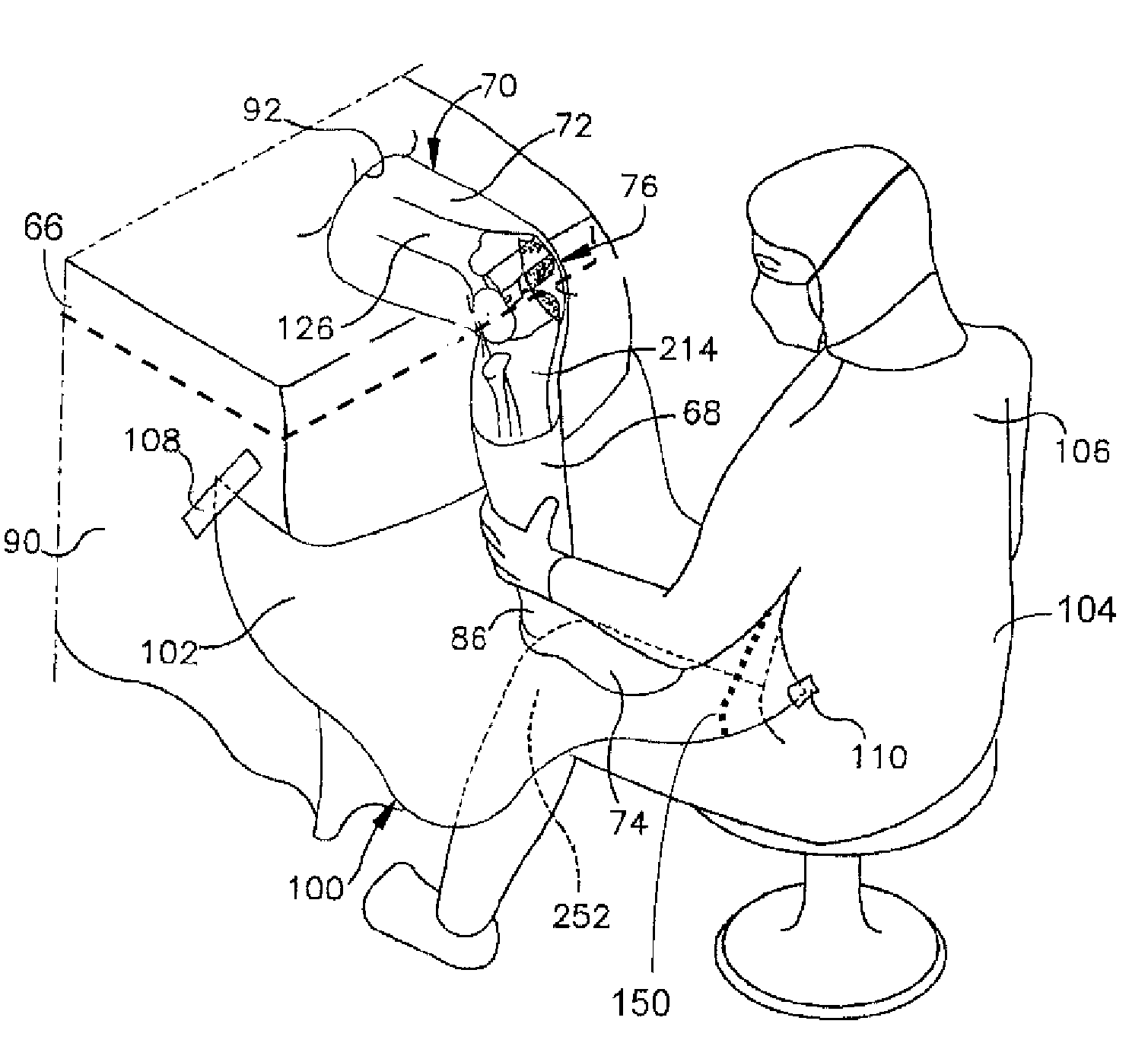
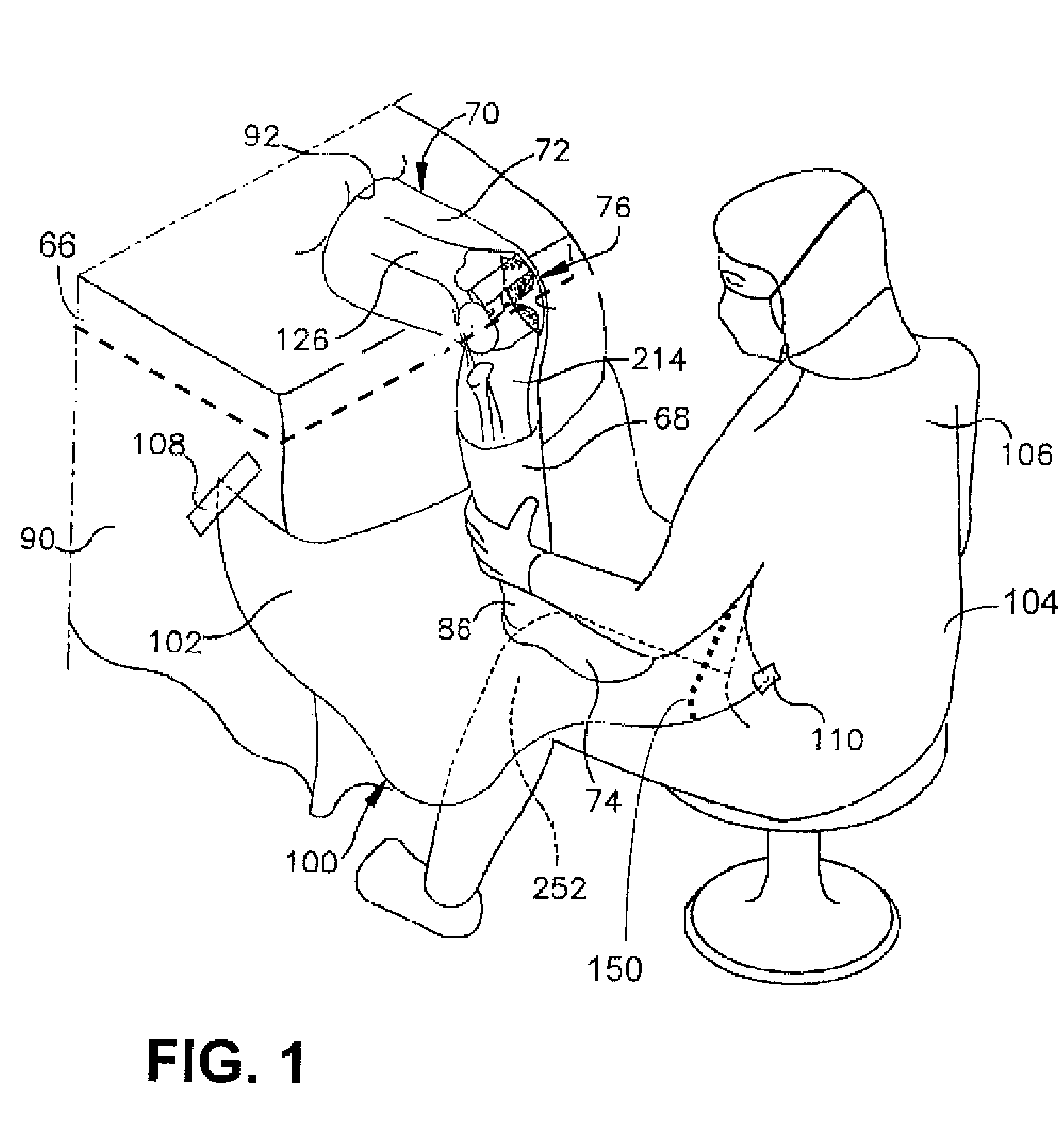
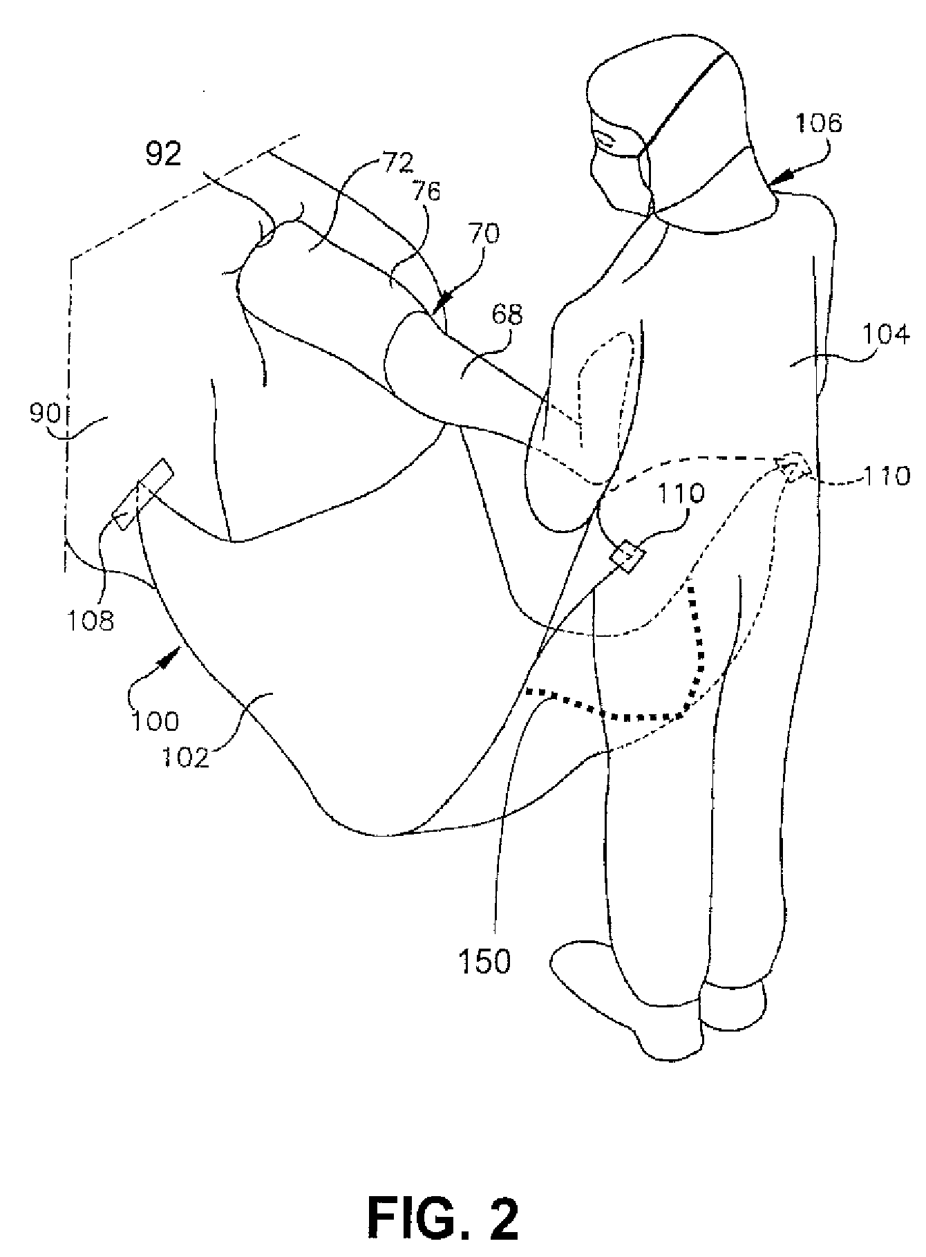
[0045]FIG. 1 shows a draping system in accordance with the present invention wherein a continuous sterile field is established below an operating table during a surgical procedure such as a knee surgery and the practitioner is seated. FIG. 2 shows a draping system in accordance with the present invention wherein a continuous sterile field is established below an operating table during a surgical procedure such as a knee surgery and the practitioner is standing. The practitioner is shown as a su...


PUM

PropertyMeasurementUnit
included angleaaaaaaaaaa
surgical areaaaaaaaaaaa
transparentaaaaaaaaaa

Abstract

A draping system provides a continuous sterile field between a patient incision area and one or more medical practitioners. The draping system has a quick release system incorporated into the drape that enables a medical practitioner to separate from the continuous sterile field without disrupting the sterile field around the practitioner or the patient. The draping system may include an abbreviated practitioner gown, a drain and an integral patient incision area or a flap for extending the continuous sterile field around to one or more additional operating room tables. A modular drape and gown system extends the sterile field beyond the operating table allowing practitioners to couple to the extended field. A tent provides an enclosed sterile field useful in mobile or other non operating room surgical environments. Integral lighting and information displays facilitate field surgical procedures.

Description

CROSS REFERENCE TO RELATED APPLICATIONS [0001] This application is a divisional of U.S. patent application Ser. No. 10 / 263,893 filed Oct. 3, 2002. The aforementioned U.S. patent application Ser. No. 10 / 263,893 is a continuation-in-part of U.S. patent application Ser. No. 10 / 191,751 filed Jul. 8, 2002, and a continuation-in-part of U.S. patent application Ser. No. 09 / 976,396 filed Oct. 11, 2001, and a continuation-in-part of U.S. patent application Ser. No. 09 / 941,185 filed Aug. 28, 2001.FIELD OF THE INVENTION [0002] This invention is related to the field of draping systems used to create and maintain sterile fields surrounding operative sites. BACKGROUND OF THE INVENTION [0003] In a medical operating room environment multiple independent and discontinuous sterile environments are established. A patient is positioned upon an operating room table and a sterile field around the area surrounds the operative site on the patient is created with one or more sterile drapes. Furthermore, med...

Claims


Application Information

Patent Timeline
Patent Type & Authority Applications(United States)
IPC IPC(8): A61B19/00A61B19/04A61B19/08A61B46/23
CPCA41D19/0157A61B17/025A61B17/0401A61B17/0487A61B17/155A61B17/157A61B17/158A61B17/1604A61B17/1666A61B17/1668A61B17/1675A61B17/1703A61B17/1717A61B17/1721A61B17/1746A61B17/1764A61B17/809A61B19/04A61B19/08A61B19/2203A61B19/38A61B19/52A61B19/5202A61B19/5212A61B19/5225A61B19/5244A61B2017/00004A61B2017/00199A61B2017/00477A61B2017/00557A61B2017/00734A61B2017/0268A61B2017/0409A61B2017/0414A61B2017/0496A61B2019/085A61B2019/086A61B2019/106A61B2019/385A61B2019/464A61B2019/502A61B2019/505A61B2019/521A61B2217/005A61B2217/007A61F2/30721A61F2/30724A61F2/30767A61F2/30771A61F2/34A61F2/38A61F2/3859A61F2/3868A61F2/3872A61F2/3877A61F2/389A61F2/4609A61F2/461A61F2/4684A61F2002/2817A61F2002/2835A61F2002/30079A61F2002/30326A61F2002/30364A61F2002/30382A61F2002/30387A61F2002/30398A61F2002/30433A61F2002/30507A61F2002/30761A61F2002/30883A61F2002/30892A61F2002/3092A61F2002/30934A61F2002/30975A61F2002/3401A61F2002/3403A61F2002/3895A61F2002/4631A61F2002/4635A61F2002/4636A61F2002/4677A61F2210/009A61F2220/0025A61F2220/0033A61F2220/0041A61F2250/0037A61F2310/00011A61F2310/00017A61F2310/00023A61F2310/00029A61F2310/00131A61F2310/00365A61G13/1245A61G13/125A61G2013/0045A61G2013/0054A61G2013/0063A61G2013/0072A61G2013/0081A61B34/20A61B34/30A61B42/00A61B46/00A61B90/30A61B90/36A61B90/361A61B90/37A61B90/40A61B2034/102A61B2034/105A61B2046/201A61B2046/205A61B2046/236A61B2090/064A61B2090/309A61B2090/401A61F2002/30331A61G13/0045A61G13/0054A61G13/0063A61G13/0072A61G13/0081
Inventor BONUTTI, PETER M.
Owner BONUTTI SKELETAL INNOVATIONS
Learn More