
Filtering device

Inactive Publication Date: 2007-05-10
WESTFALIA SEPARATOR AG
View PDF6 Cites 0 Cited by
  • Summary
  • Abstract
  • Description
  • Claims
  • Application Information

AI Technical Summary

Benefits of technology

[0003] This arrangement has been successful. Nevertheless, there is demand for a filtering device with filtering disks, particularly diaphragm disks, which permits or has a good filtering effect, while the construction is particularly simple, and preferably has a low energy consumption.
[0005] The filtering device of the present disclosure is characterized by a simple construction with a stationary non-rotatable container, a low energy requirement and the filtering effect is good.
[0007] The overlapping area provides a particularly low risk of the formation of a covering layer of solids on the diaphragm disks and thereby increases a sanitary suitability or design.
[0008] The inflow leads tangentially into the container which is cylindrical at least in sections. This results in a preliminary separation because of the centrifugal effect and in a possibility of being the sole or additional drive of the diaphragm plates with the spindles by the circulating liquid.
[0012] The container may be hydrocyclonically shaped. In a particularly favorable manner, this achieves a preliminary separation of solid particles which results in a minimized action of solids upon the diaphragm plates. As a result of the turbulence of the spindles and the diaphragm plates toward the outside, or away from the diaphragms of the diaphragm plates, the solids retained by the diaphragm surfaces are carried away downward by gravity.

Problems solved by technology

This results in a preliminary separation because of the centrifugal effect and in a possibility of being the sole or additional drive of the diaphragm plates with the spindles by the circulating liquid.

Method used


Image

  • Filtering device
  • Filtering device

Examples


Embodiment Construction

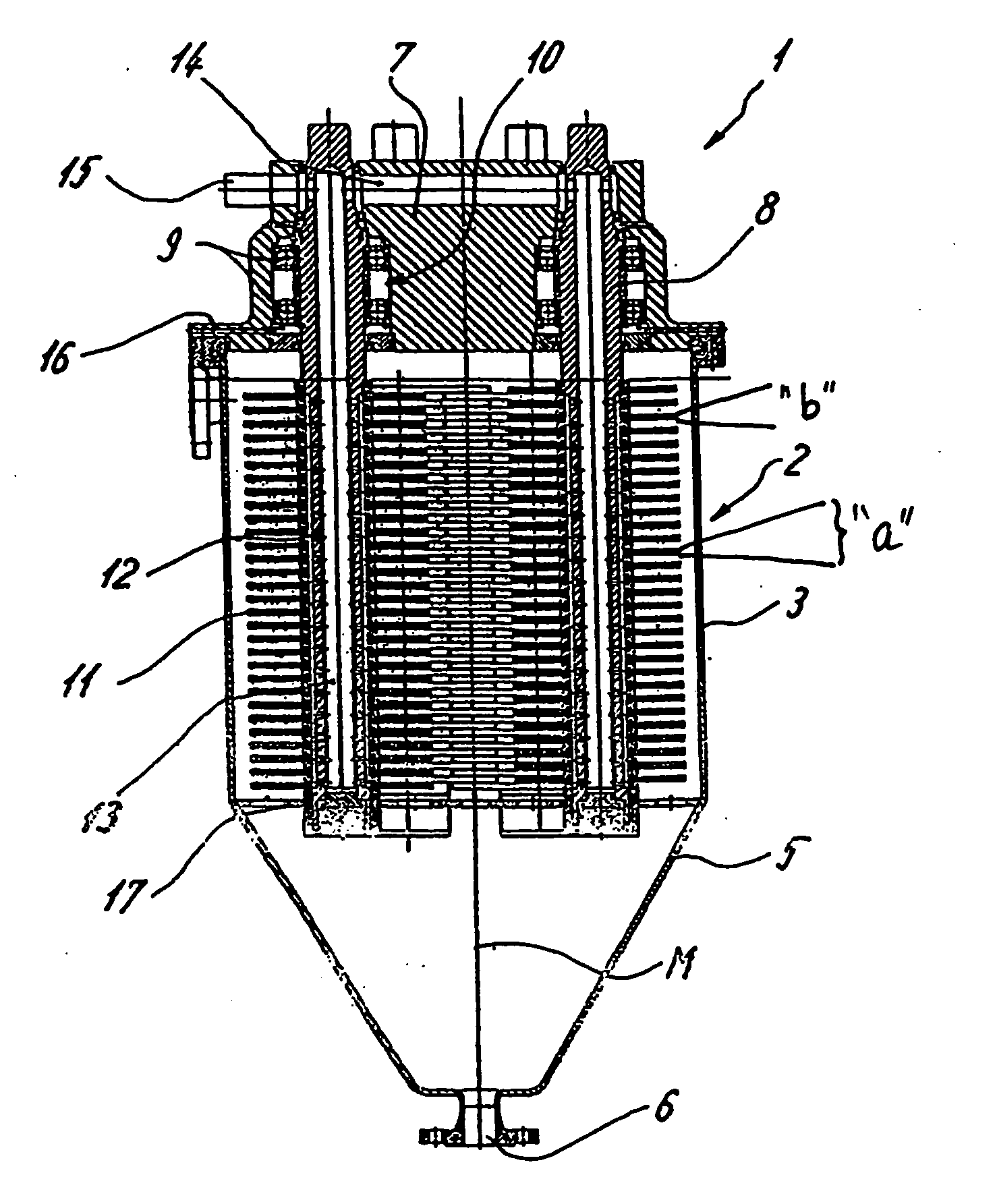
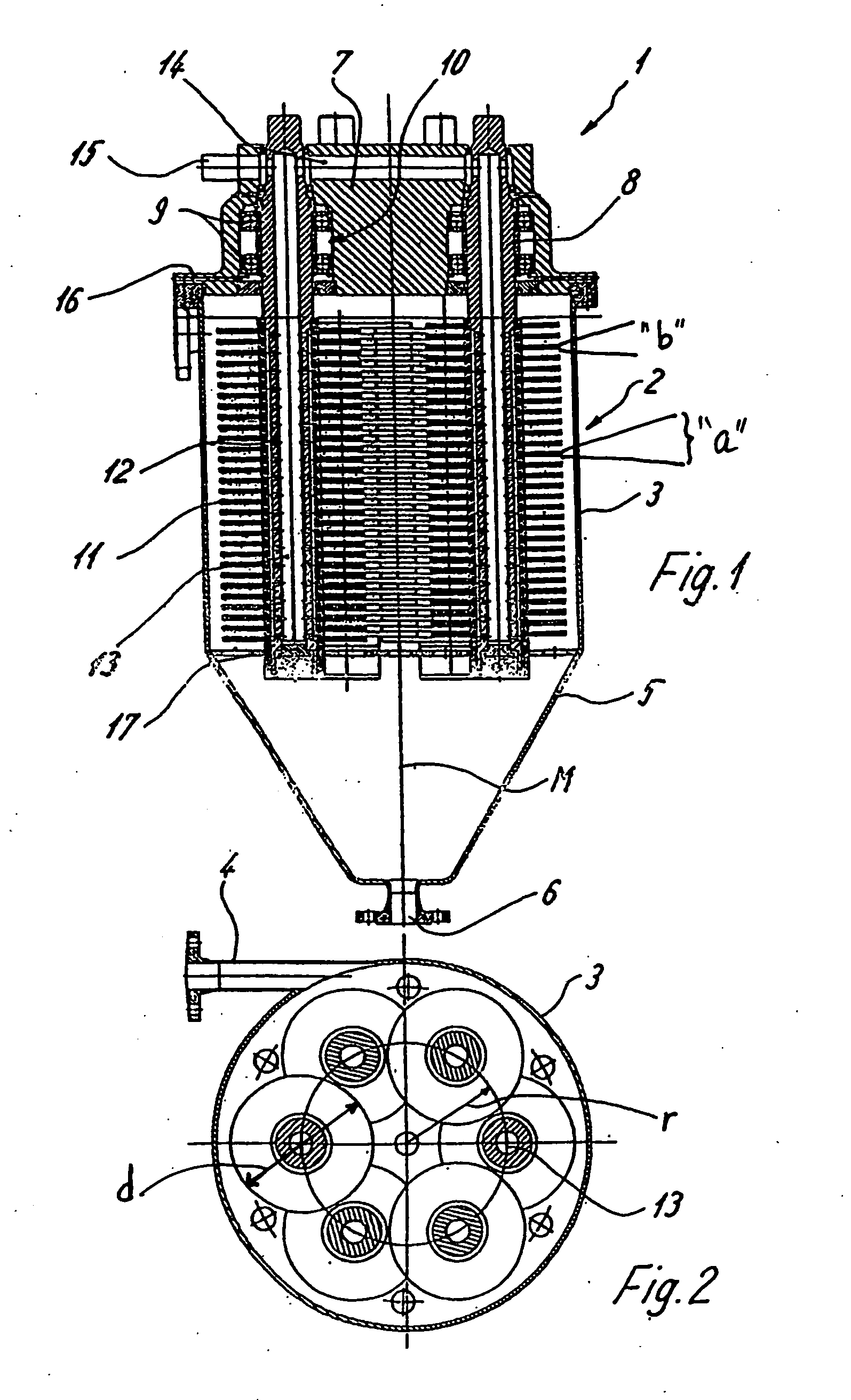
[0016]FIG. 1 illustrates a filtering device 1 with a stationary non-rotatable container 2 which is hydrocyclonically shaped. A cylindrical section 3 of the container 2 has a center axis M oriented perpendicularly or vertically and has a tangentially oriented inlet 4. Cylindrical section 3 is adjoined in a downward direction by a tapering conical section 5 which leads into an outlet 6 in a downward direction.

[0017] Because of the tangential inlet 4, a motor drive can be eliminated if product inflow speed is sufficient. That is because a forming twist drives diaphragm plates or disks 11 as a result of developing friction. However, for supporting a rotating movement, a drive (shown in phantom in FIG. 2) can optionally be utilized which has a motor with a belt transmission (not shown).

[0018] The container 2 or its cylindrical section 3 is closed on its top side by a type of lid which simultaneously is used as a bearing housing 7 for several spindles 8 . The spindles 8 project from abo...


PUM

PropertyMeasurementUnit
Thicknessaaaaaaaaaa
Diameteraaaaaaaaaa
Shapeaaaaaaaaaa

Abstract

A filtering device includes a container having an inlet and two or more spindles arranged in the device. Further included are at least two mutually axially offset diaphragm plates mounted on each of the two or more spindles. The two or more spindles are distributed in the container and rotatable relative to the container.

Description

BACKGROUND AND SUMMARY [0001] The present disclosure relates to a filtering device having a container with an inlet. At least one spindle is arranged in the device. A plurality of mutually axially offset diaphragm plates are mounted on the spindles. [0002] Filtering devices of this type are known. For example, from the field of separators it is known to place axially mutually offset diaphragm plates on the inlet pipe. [0003] This arrangement has been successful. Nevertheless, there is demand for a filtering device with filtering disks, particularly diaphragm disks, which permits or has a good filtering effect, while the construction is particularly simple, and preferably has a low energy consumption. [0004] The present disclosure addresses the above-referenced need by providing for a filtering device, that includes a container having an inlet and two or more spindles arranged in the device. Further included are at least two mutually axially offset diaphragm plates mounted on each of...

Claims


Application Information

Patent Timeline
IPC IPC(8): B01D29/46B01D29/52B01D33/21B01D63/16
CPCB01D33/21B01D63/16B01D33/37B01D33/68B01D33/727
Inventor MACKEL, WILFRIEDHELGA, TIETZ
Owner WESTFALIA SEPARATOR AG
Features
  • Generate Ideas
  • Intellectual Property
  • Life Sciences
  • Materials
  • Tech Scout
  • Unparalleled Data Quality
  • Higher Quality Content
  • 60% Fewer Hallucinations
Learn More